
TM 10-3510-226-23
0018 00
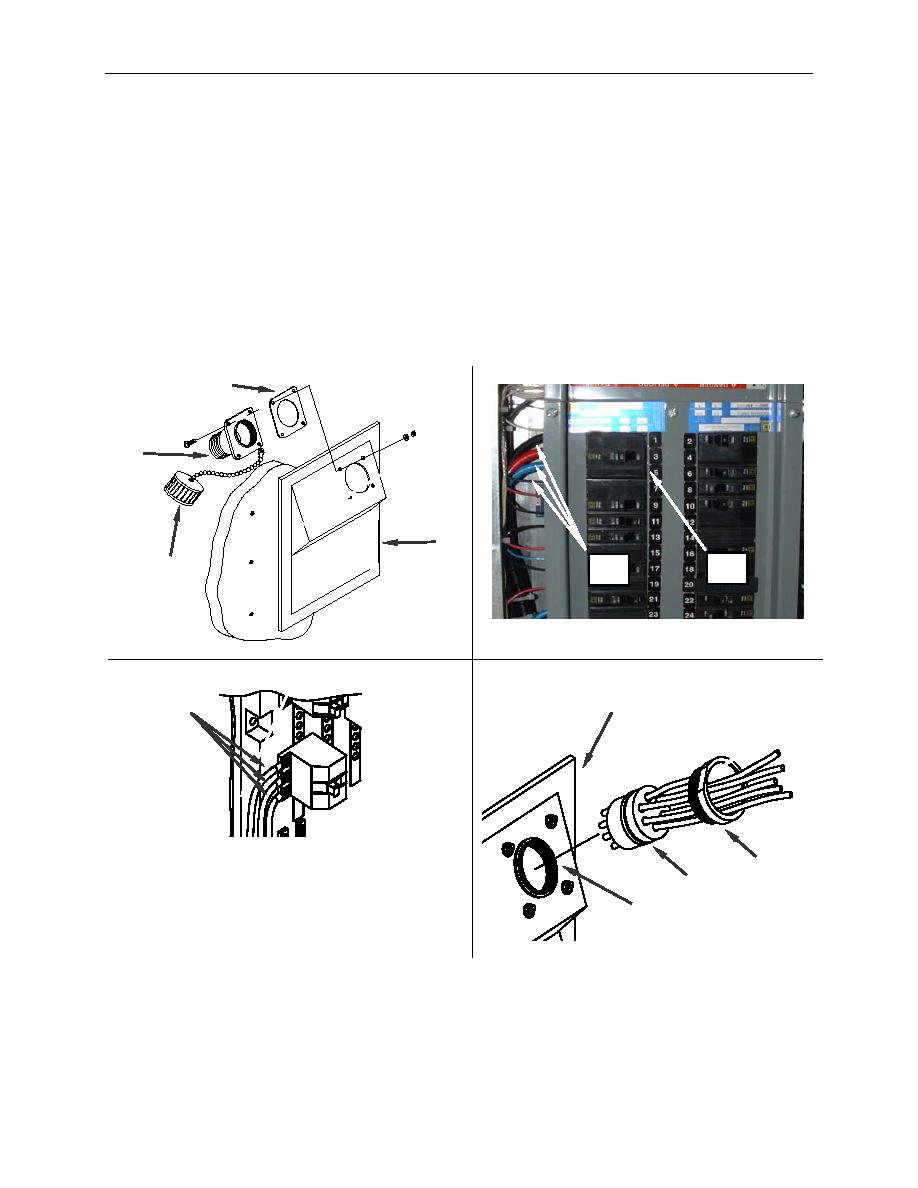
REPLACE-CONTINUED
6. Remove screws, washers and nuts securing the connector sleeve (Figure 4, Item 6), gasket (Figure
4, Item 13) and dust cover (Figure 4, Item 14) to the power panel (Figure 4, Item 3).
7. Tag and disconnect the wires (Figure 4, Item 10) from the main circuit breaker (Figure 4, Item 12), if
replacing the main power input connector, or from the dryer circuit breaker if replacing one of the
dryer circuit breakers.
8. Install the replacement connector sleeve (Figure 4, Item 6), gasket (Figure 4, Item 13) and dust
cover (Figure 4, Item 14) to the power panel (Figure 4, Item 3)
9. From the rear of the power panel (Figure 4, Item 3), push the replacement receptacle (Figure 4,
Item 2) into the sleeve (Figure 4, Item 6) and secure with the retainer (Figure 4, Item 5).
13
6
3
12
14
10
3
10
5
2
6
Figure 4. Replace the Power Input Receptacle.
0018 00-5

