
(2) Pressure setting adjustment.
(j) Pressure adjustment is made by turning
adjusting screw clockwise to increase cutout pressure
NOTE
and counterclockwise to decrease cutout pressure, using
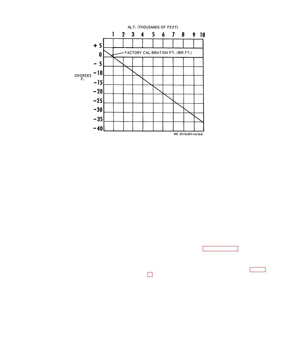
The water pressure control is set
an offset screw driver.
to energize the fuel solenoid valve
at 10-15 P.S.I.G. water pressure,
(k) After each change in the pressure
and deenergize the fuel solenoid
adjusting screw steps (f) and (g) should be repeated.
valve at 6 P.S.I.G. pressure.
Pressure adjusting screw locking nut should be
(a) Remove hose quick connector from water
tightened after each change in adjustment screw.
header and close off end of header with 1 /2 inch I.P.S.
(I) After correct pressure setting is obtained
pipe cap (fig. 6-4B).
(fuel solenoid valve energized at 10 to 15 P.S.I.G.),
(b) Remove temperature bulb from header
remove pressure gauge, elbow and 3/8 inch nipple.
and install l/2 inch pipe nipple, reducing ell and pressure
Reinstall temperature bulb and tighten compression
gauge (fig. 6-4B).
fitting. Remove 11/2 inch pipe cap, and reinstall hose
quick connector.
(c) Install hose to quick connector at outlet of
globe valve (fig. 6-4B) and allow hose to lay on ground.
The fuel pump, located on the lower left end of the water
(d) With l/2 inch globe valve fully open, turn
heater, draws fuel from the fuel drum and forces it to the
on water supply.
burner.
a. Removal. Refer to paragraph 4-41 and remove
(e) Turn fuel pump motor switch on.
the fuel pump from the water heater.
(f) Slowly close 11/2 inch globe valve in
b. Disassembly.
water header and observe pressure gauge when
pressure control energizes fuel solenoid valve.
(1) Remove the eight cover screws (1, fig. 6-
(g) Slowly open globe valve and observe
remove the cover and the gasket (3) from the fuel pump
pressure gauge reading when fuel solenoid valve is de-
body.
energized.
(2) Remove the strainer (4) from the body.
(h) To make pressure adjustments, remove
cover from pressure-temperature control.
(3) Remove the five end plate screws (5)
from
(i) Loosen hex nut that locks the pressure
adjusting screw at the bottom right side of the controller
case (fig. 6-4C).

