
11.0
COMPONENT SERVICING INFORMATION
This section was developed to assist the operator or service personnel in service, repair or re-
building of serviceable components. Items not covered in this section are either nonrepairable,
or more economical to replace.
11.1
Installation of Hydro/Fuel Safety Modulator Repair Kits
NOTE: Before attempting these procedures, cool down and stop "cleaner as per paragraph 7.0. Dis-
connect main electrical power source and open cleaning gun valve to relieve all discharge pressures.
Close Soap Tank Fill-Mix Valve and Fuel Filter Valve.
A.
Remove the Hydro/Fuel Safety Modulator assembly as a unit by removing tubing flare nut fit-
tings and removing assembly at pipe union.
B.
Unscrew Adjusting Cap (item 10) to relieve all Spring (item 11) pressure off of Diaphragm
(item 3). Remove Cap Screws (item 1) and lift off Cover (item 4), marking cover and body to
assure proper reassembly and tube fitting alignment.
C.
Remove old Diaphragm (item 3) and Diaphragm Gasket (item 2) and clean resting surfaces of
Cover (item 4) and Valve Body (Item 8).
D.
Install new Diaphragm (item 3), new Gasket (item 2) and old Cover (item 4) in that order,
using care not to nick or scratch mating surfaces, then install and carefully tighten Screws
(item 1) evenly to assure a high pressure seal, Reinstall assembly on cleaner.
NOTE:
Whenever replacing this Hydro/Fuel Safety Modulator, be sure flow arrow is in direction of
normal fuel oil flow . . . from fuel pump towards burner.
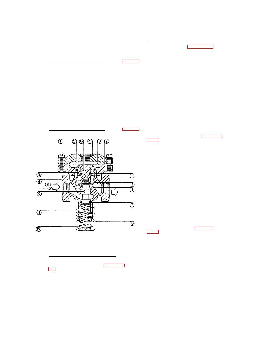
11.1.2 Installing Repair Kit #1178-K2 (Reference Figure Below)
A.
Same procedure as A, B and C of Paragraph
11.1.1 above.
B,
Retighten Adjusting Cap (item 10) to raise
Valve Assembly (item 6) and item 9) to full
open position. Pull out Plunger (item 6)
free of Valve Body (item 8) and use wide
blade screw driver to unscrew Plunger Cup
(item 12), and pull out Valve Assembly
(item 9).
c.
Remove Brass Washer (item 14), old Plunger
Disc (item 13) and O-Rings (items 5 & 7 ).
Grease new O-rings and install on Valve
(item 9) and Plunger (item 6), avoiding
O-ring distortion.
D,
Install new Plunger Disc (item 13) and Washer
(item 14) round face up as indicated on
Valve (item 7), then reinstall Plunger Cup
(item 12).
E.
Remove Adjusting Cap (item 10) and old Spring
(item 11), Insert Plunger (item 6) using
care to avoid distortion of O-ring and re-
assemble Diaphragm (item 3), Gasket (item 2),
and Cover (item 4) , as per paragraph
Install new Spring (item 11) and Adjusting
F.
HYDRO/FUEL SAFETY MODULATOR
Cap (item 10) and reinstall assembly to cleaner.
Part No. 1178-01
Re-attach tubing at elbow fittings. Be sure washer
(item 15) is installed as shown.
NOTE: Bleed pressure line of all air by loosening
11.1.3 Adjusting Hydro/Fuel Safety Modulator
flare nut at fitting on Cover (item 4), and open
Fuel Filter Valve.
To readjust the Hydro/Fuel Safety Modulator
follow procedure as outlined in paragraphs

