
TM 10-3510-226-10
0003 00
Electrical System
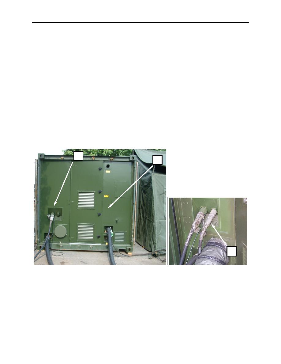
The CBL receives 208 VAC power from a 100 kW generator or approved municipal power source through
three 100A cables. One cable feeds the power service panel at the washer end (Figure 7, Item 1) of the
container. Two cables feed the dryer power service panel located on the service panel at the dryer end
(Figure 8, Item 2) of the container.
The power service panel (Figure 7, Item 3) at the washer end of the container distributes power to the
main circuit breaker panel (Figure 8, Item 4). Power is then distributed through circuit breakers to the
washers, exhaust fans, CBL lighting, source water pump, soap dispenser, PLC, water boiler, and filtration
system pumps. Service outlet receptacles (Figure 8, Item 5) that are GFCI protected are located at each
end of the container and at the center for powering work lights and other external components. A 60A
outlet (Figure 7, Item 6) is provided for powering the FDECU, ASH, TEMPER lighting, and utility
receptacles. All outlet receptacles are controlled and protected by the main circuit breaker panel.
The dryer power service panel (Figure 8, Item 7) distributes power from the two 100A cables to the dryer
breaker panel (Figure 9, Item 8). Power is then distributed to each dryer through circuit breakers.
Operating control for most electrical components is centralized at the Programmable Logic Control (PLC)
(Figure 9, Item 9). In the event of a failure of this component, all systems can be either bypassed or
manually operated.
3
1
6
Figure 7. Electrical System.
0003 00-7
