TM 10-3510-226-23
0018 00
TEST-CONTINUED
8. Use an ohmmeter to check for zero resistance between each prong (Figure 2, Item 9) and the
corresponding wire connection (Figure 2, Item 10) on the dryer circuit breaker (Figure 2, Item 11) if
testing a dryer power input receptacle, or the main circuit breaker (Figure 2, Item 12) if testing the
main power input receptacle.
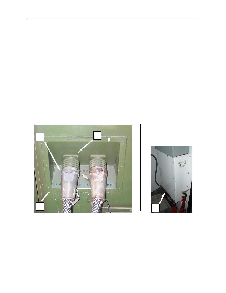
9. Check for secure connection and condition of wiring (Figure 1, Item 10) with an open connection
between the prong (Figure 2, Item 9) on the receptacle (Figure 1, Item 2) and the main circuit
breaker (Figure 2, Items 11 or 12).
10. Replace a receptacle (Figure 2, Item 2) or wiring (Figure 2, Item 10) with an open connection.
11. If continuity is determined between each prong and the corresponding circuit breaker connection, re-
install the receptacle (Figure 2, Item 2), and secure with retainer (Figure 2, Item 5).
12. Install the panel cover (Figure 1, Item 4).
13. Reinstall circuit breaker panel cover (Figure 2, Item 7) and circuit breaker box cover (Figure 2, Item
8).
14. Connect the power input cable (Figure 1, Item 1).
2
1
3
4
Figure 1. Test the Power Input Receptacle.
0018 00-2


