TM 10-7360-226-13&P
0005 00
CONTAINERIZED KITCHEN (WITH TRAILER)
DESCRIPTION OF OPERATOR CONTROLS AND INDICATORS
OPERATION
SET UP
1. Press PO ER button.
W
For manual fueling - see operating
2. Turn burner control to high
instructions.
(Start) position.
1.
Install MBU in appliance.
M BU
3. Press START button
2.
Connect 24 Volt DC powercable
4. When run indicatorlight is on, turn
to rear of MBU.
burner control to desired setting.
3.
Connect fuel hose to front of MBU
5. In case of Automatic shut down
and fuel supply.
see operating instructions.
4.
Press PO ER button.
W
SHUTDOWN
5.
Press FUEL button.
1. Press STOP button.
6.
When fuel indicator light is steady
2. Press PO ER button.
W
green - Disconnect hose.
7.
Press PO ER button.
W
6
5
Run
7
1
HIGH
LOW
Warm Up
START
(Start)
8
Fueling/Fuel
WARNING
9
CARBON MONOXIDE EM ISS IONS
2
Low Fuel
ENSURE AD EQUATE VENTILATION
DURING OPERATION.
10
STOP
Voltage
ALLOW EQUIPM ENT TO COOL
BEFORE HANDLING
11
Service
2 P ERSON LIFT - 68 lb M AX
3
Fuel
TOTAL HOURS
12
Manufactured by
4
Te l e f l e x
Power
Canada Ltd.
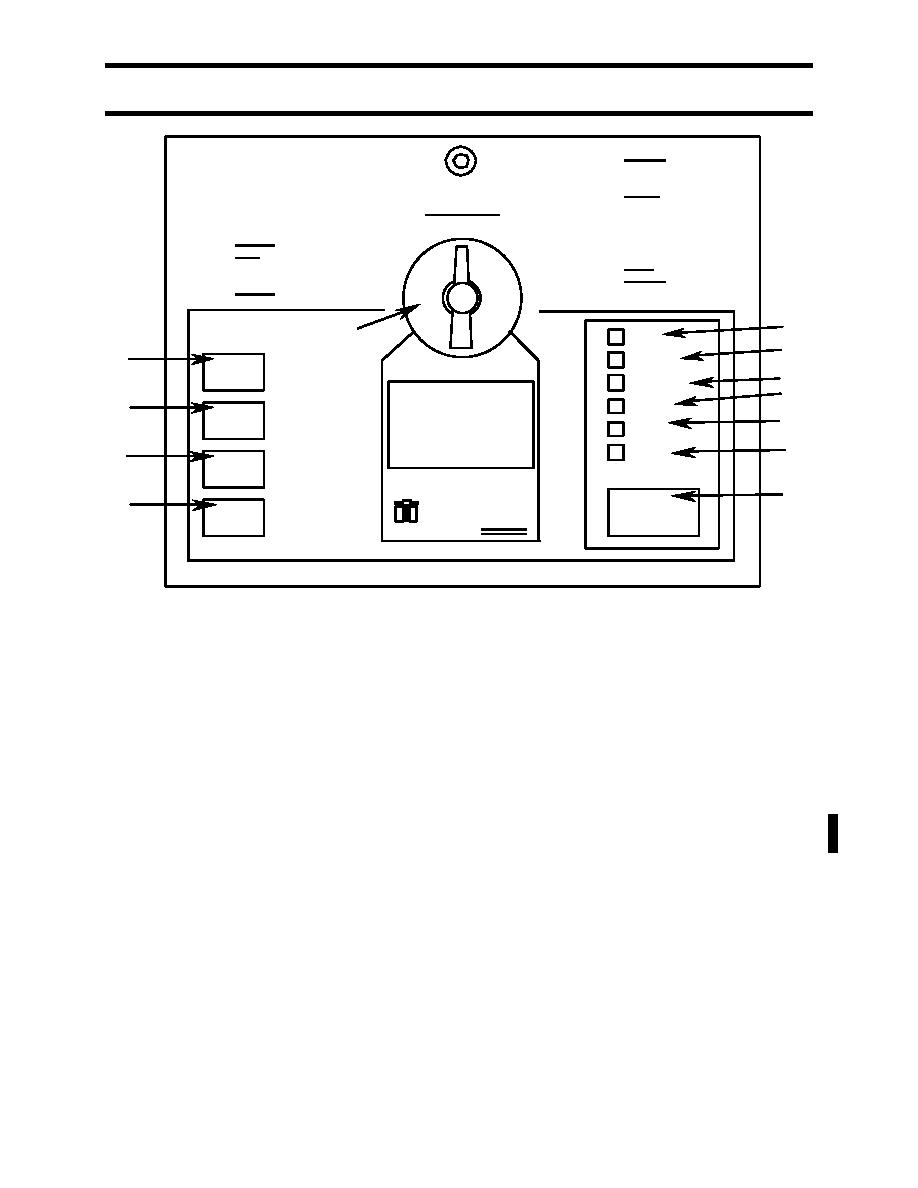
Figure 6. MBU Control Panel.
Appliance Control Box
The appliance control box, Figure 7, is located in the food preparation area. It is stored for
packout, and is hung from one of the fabric arch supports for operation. It houses the control
switches for the hand sink assembly water pump and water heater, and the tray pack heater
fan. The controls include:
WATER PUMP switch (1): ON/OFF toggle switch for the hand sink water pump.
Circuit breakers (2): Pop out on overload. Push in to reset.
HEATER FAN switches (3, 4): ON/OFF toggle switches for the tray pack heater fan.
Only one switch is used for operation; the other is a spare.
WATER HEATER switch (5): ON/OFF toggle switch for the hand sink water heater.
Receptacles (6): Electrical connections for the appliances. Each appliance
connection corresponds to the switch above it.
0005 00-7
Change 1


