Home
Download PDF
Order CD-ROM
Order in Print
Figure 4-62. Compressor starter switch, removal and installation
Section XVIII. AIR CYLINDER AND RELATED PARTS
TM-10-3510-208-12 - index
Page Navigation
152
153
154
155
156
157
158
159
160
161
162
TM
10-3510-208-12
TS
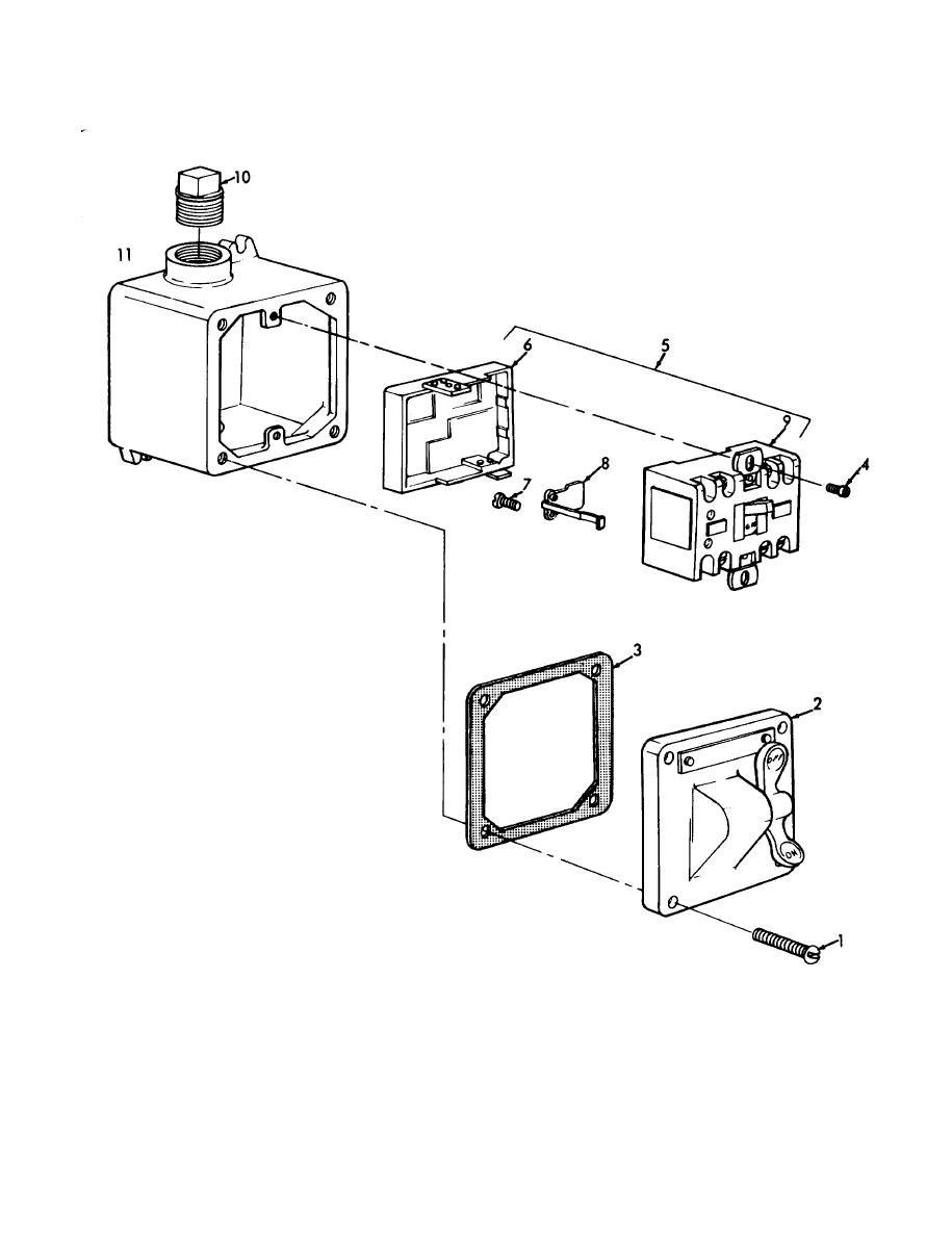
3S10-208-12/4-63
8.
Heater
5. Switch
assembly
1.
Screw
9.
Switch
6.
Cover
2.
Cover
10.
Plug
7.
Screw
3.
Gasket
11.
Box
4.
Screw
Figure
4-63.
Compressor
starter
switch
unit,
disassembly
and
reassembly.
4-85