Home
Download PDF
Order CD-ROM
Order in Print
Figure 2-14. Compressor on-off switch, removal and installation
Figure 2-16. Compressor air supply tank, air lines, removal and installation
TM-10-3510-208-34
Page Navigation
26
27
28
29
30
31
32
33
34
35
36
TM 10-3510-208-34
TS 10-3510-208-34/2-15
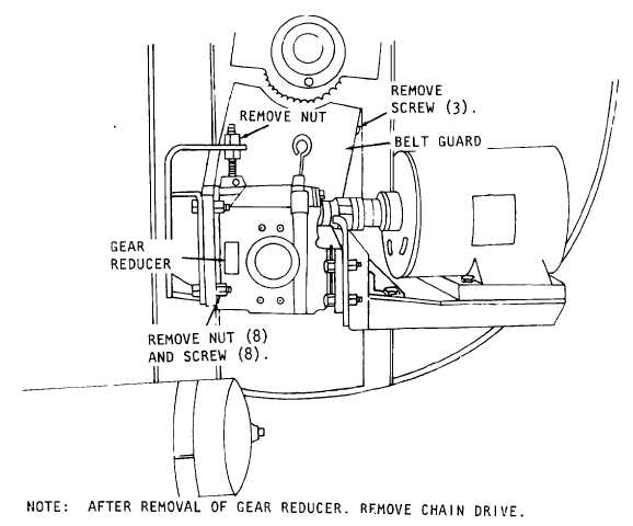
Figure 2-15. Gear reducer. removal and installation.
(4)
Refer to figure 2-16 and disconnect
the air lines from the air supply tank.
2-23