TM 10--3510--221--24
0011 00--5/6 blank
LAUNDRY ADVANCED SYSTEM
TROUBLESHOOTING AIDS AND SUPPLEMENTARY DATA -- Continued
0011 00
TABLE 1. Solid--State Relay Data -- Continued.
PCB# POSITION
FUNCTION
INPUT
VOLTAGE
OUTPUT
VOLTAGE
14
Drum A Door Lock (DN100A) Solenoid Valve
(SV115A)
+5 VDC
+12 VDC
15
Still Door Locks (DN200) Solenoid Valve (SV200)
+5 VDC
+12 VDC
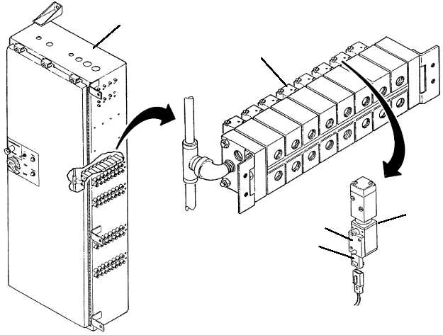
SOLENOID VALVE MANIFOLDS
There are four solenoid manifolds (1) located in the main control enclosure (2). Each manifold has eight solenoid
valves (3) that are used to control air flow to and from the air driven components (i.e., air--actuated ball valves, brake
intensifiers, damper air cylinders, and door lock air cylinders). Each solenoid valve has an LED (4). The LED will turn
on when power is applied to the solenoid valve and will turn off when power is removed. Knowing the status of the
LED will help determine if the problem is caused by an electrical circuit failure or an air system failure. In addition
each solenoid valve contains a manual operator (5). When the manual operator is pressed the air driven component
will actuate provided air pressure is available. Using the manual operator will help determine if the problem is caused
by the solenoid valve or by the air driven component.
2
3
5
4
3
ROTATED 90
END OF WORK PACKAGE


