
TM 10-3510-226-23
0035 00
ADJUST-CONTINUED
Adjust the Pressure Relief Valve
NOTE
The system pressure may be monitored at the PLC.
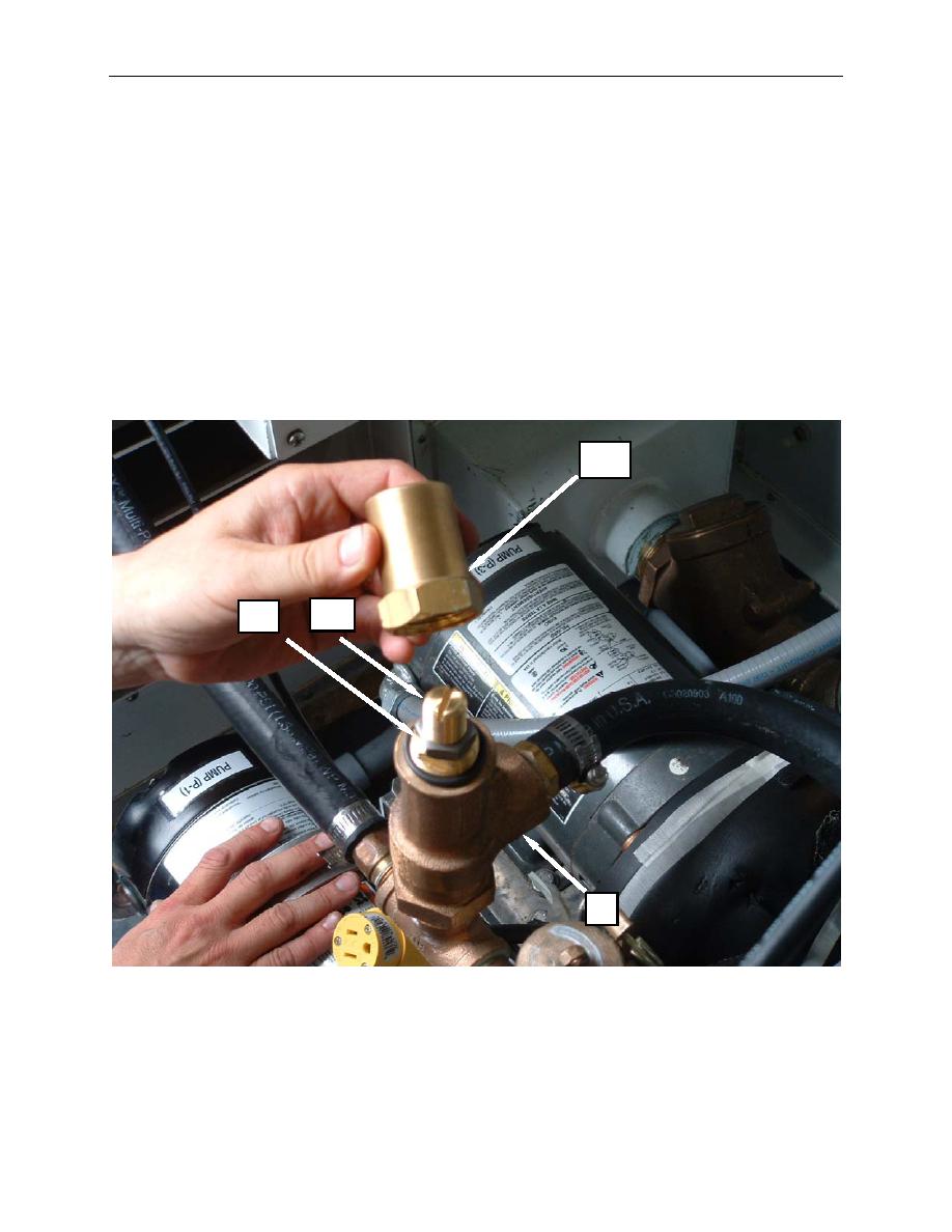
1. Remove the cap (Figure 4, Item 11) from the pressure relief valve (Figure 4, Item 8).
2. Loosen the locknut (Figure 4, Item 12).
3. Turn the adjustment screw (Figure 4, Item 13) clockwise to increase relief pressure or counter-
clockwise to decrease relief pressure.
4. Tighten the locknut (Figure 4, Item 12), and install the pressure relief valve cap (Figure 4, Item 11).
11
13
12
8
Figure 4. Adjust the Pressure Relief Valve.
0035 00-6
