TM 10-3510-226-23
0036 00
REPLACE-CONTINUED
Replace the Pressure Relief Valve
WARNING
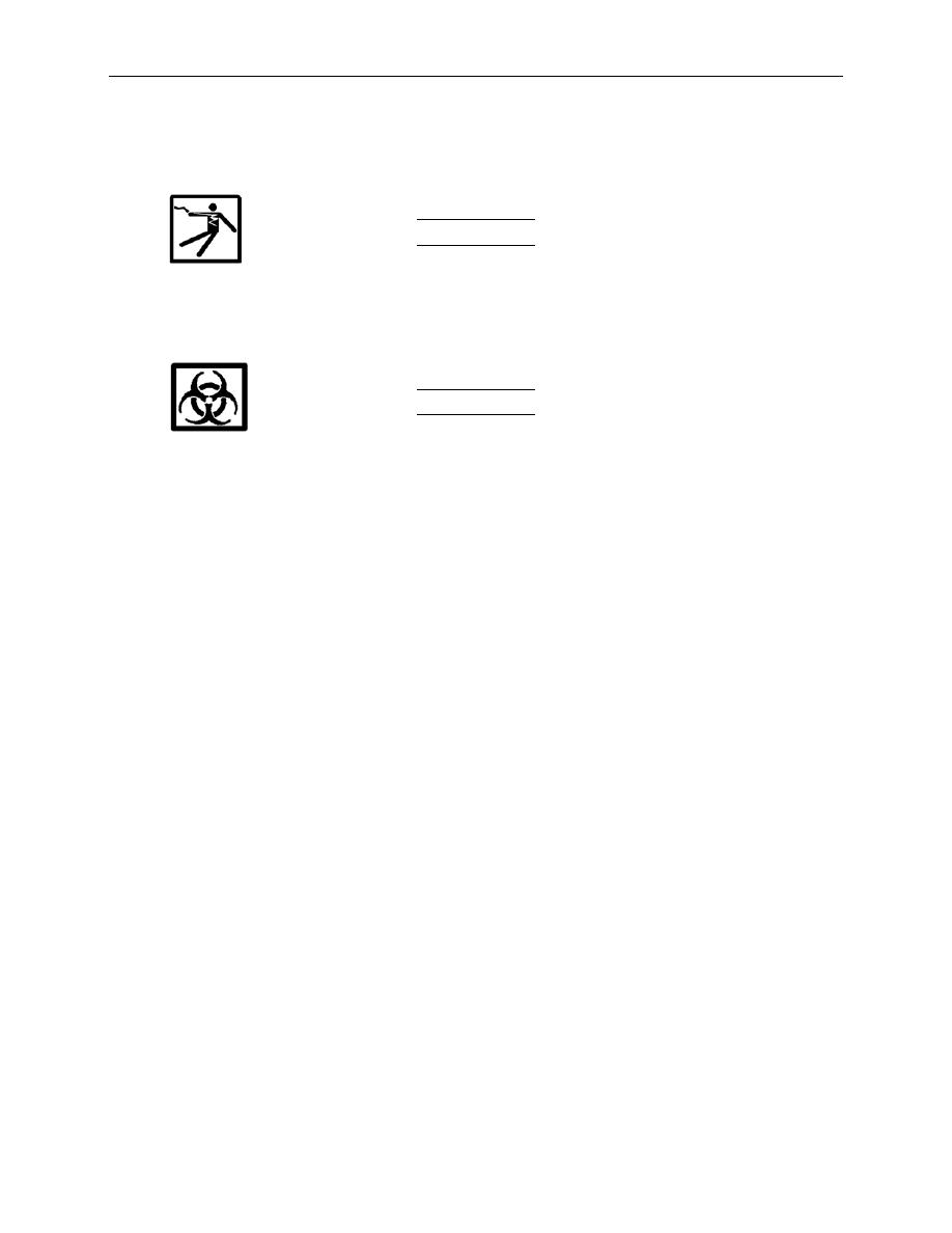
This component operates close to electrical equipment. Remember that the CBL is a wet
environment. Use extreme caution, observe all warnings, and follow all safety
procedures. Failure to observe safety precautions may result in injury or death to
personnel.
WARNING
Ensure graywater pipes have been sanitized IAW procedures contained in TB MED 577
before attempting any repairs. Failure to observe safety precautions may result in
serious illness or death from biohazards.
1. Switch P-1 pump circuit breaker No. 7 and 9 to OFF.
2. Relieve pressure from system, and open pump drain (Figure 2, Item 4).
3. Loosen hose clamp retaining the pressure relief valve hose (Figure 2, Item 5) to the pressure relief
valve (Figure 2, Item 6).
4. Disconnect pressure relief valve hose (Figure 2, Item 5) from the pressure relief valve (Figure 2,
Item 6).
5. Make a note of the position of the pressure relief valve (Figure 2, Item 6), use a pipe wrench to
steady the attached pipe fittings, and remove the pressure relief valve.
6. Apply pipe sealer compound to the male threads of the replacement pressure relief valve (Figure 2,
Item 6) or the attaching male pipe fittings or nipple.
7. Install the replacement pressure relief valve (Figure 2, Item 6), ensuring the replacement valve is
both tight and correctly aligned.
8. Install pressure relief valve hose (Figure 2, Item 5) onto pressure relief valve (Figure 2, Item 6) and
retain with hose clamp.
9. Close pump drain (Figure 2, Item 4).
10. Switch circuit breaker No. 7 and 9 to ON. Operate IAW procedures given in TM 10-3510-226-10 and
monitor for normal operation.
11. Adjust pressure relief valve as necessary.
0036 00-4


