TM 10-3510-226-23
0038 00
REPLACE-CONTINUED
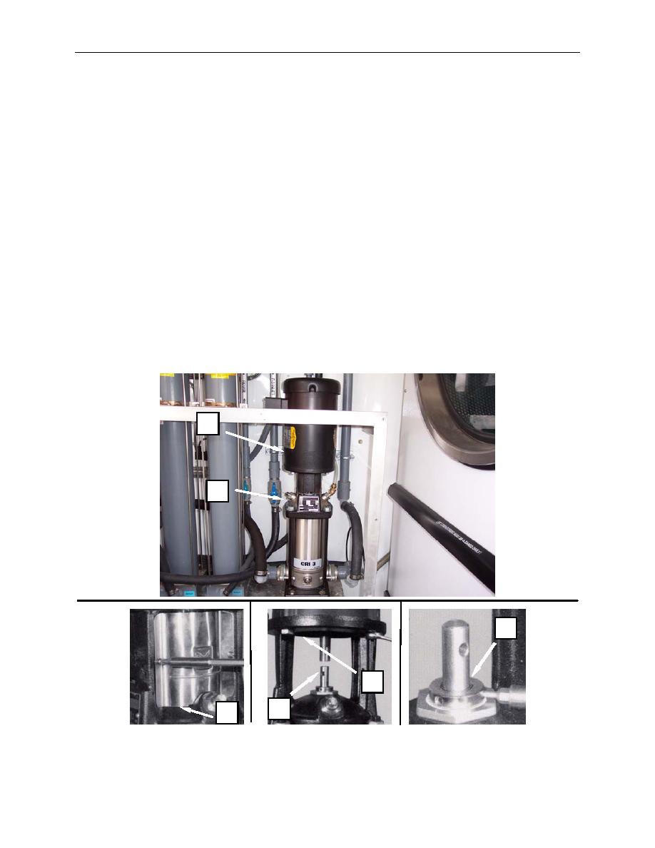
14. Install the pump head and motor stool (Figure 7, Item 6) and retain with nuts.
15. Install a new O-ring onto the cartridge seal (Figure 7, Item 7), and install the cartridge seal. Do not
tighten the setscrews.
16. Install the motor (Figure 7, Item 2) onto the motor stool (Figure 7, Item 6) and retain with bolts.
17. Install conduit and retain with locknut. Reconnect motor leads.
18. Install coupling pin to pump shaft (Figure 7, Item 5).
19. Install the coupling halves (Figure 8, Item 4) and secure in place with bolts. Align motor shaft
keyway (Figure 8, Item 4).
20. Tighten the cartridge seal (Figure 7, Item 7) securing setscrews.
21. Install the coupling guard (Figure 7, Item 3) and retain with screws.
22. Operate pump IAW procedures given in TM 10-3510-226-10, and monitor for normal operation.
23. Install guard panel.
2
1
7
6
5
3
Figure 7. Replace the Pump Impellor.
0038 00-9


