
TM 10-7360-226-13&P
0002 00
CONTAINERIZED KITCHEN (WITH TRAILER)
EQUIPMENT DESCRIPTION AND DATA
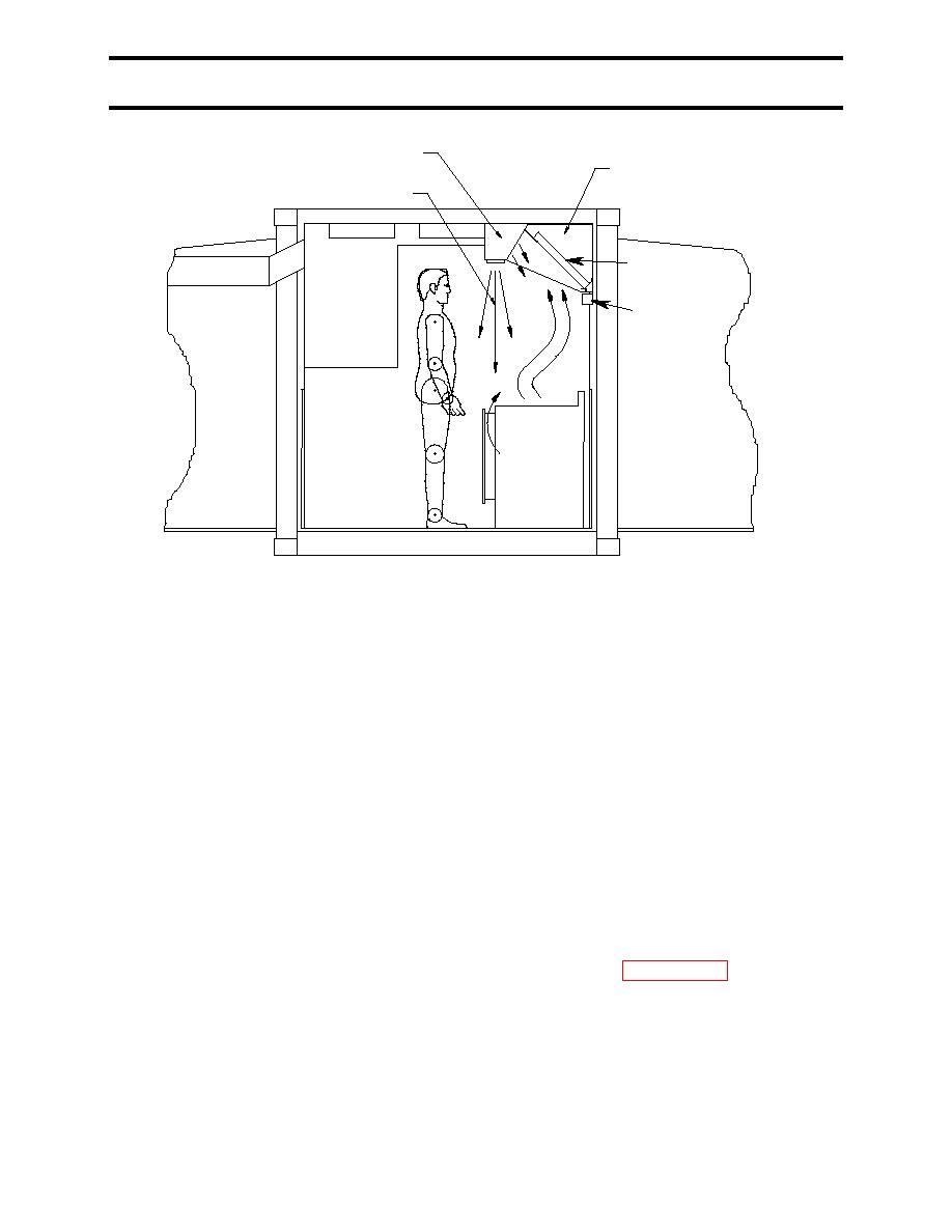
DUCT FROM MAKEUP AIR FAN
DUCT TO EXHAUST FAN
AIR CURTAIN
GREASE
FILTERS
GREASE CUP
Figure 14. Cook Center Exhaust Hood.
The exhaust hood includes removable, washable, aluminum baffle-type grease filters. A tilted
grease trough beneath the filters collects grease and directs it to a removable collection cup.
Air supply and exhaust are provided by two identical, variable-speed fans located in the
mechanical room. Under normal conditions, the fans operate at approximately 60 to 75%
capacity. The remaining capacity provides for unusual conditions when large amounts of smoke
or steam must be exhausted from the kitchen.
Environmental Control System - ECU
The Environmental Control System consists of two dual-stage air conditioners located in the
mechanical room, three heating elements located in the air conditioner evaporator discharge
plenum, fixed and removable ductwork, filters, and an Environmental Control Unit (ECU).
Components of the ECU include a wall-mounted mode selector switch in the food preparation
area and a controller mounted on the back wall inside the mechanical room.
Each air conditioner has a rated cooling capacity of 24,000 BTU/hr, and contains two
independent compressors. Under the control of the ECU, the four compressors operate
independently to provide staged cooling capacities of 12,000 BTU/hr, 24,000 BTU/hr, 36,000
BTU/hr, and 48,000 BTU/hr. ECU operation is described in detail in WP 0003 00.
When the heaters are operating, one air conditioner fan runs to circulate the heated air. The
heaters are designed to provide only limited control of kitchen temperature without overloading
Change 2
0002 00-13
