
TM 10-7360-226-13&P
0006 00
CONTAINERIZED KITCHEN (WITH TRAILER)
OPERATION UNDER USUAL CONDITIONS
4. Retrieve the jack/winch handles from their storage location on the side of the rifle rack, to the
left just inside the personnel door.
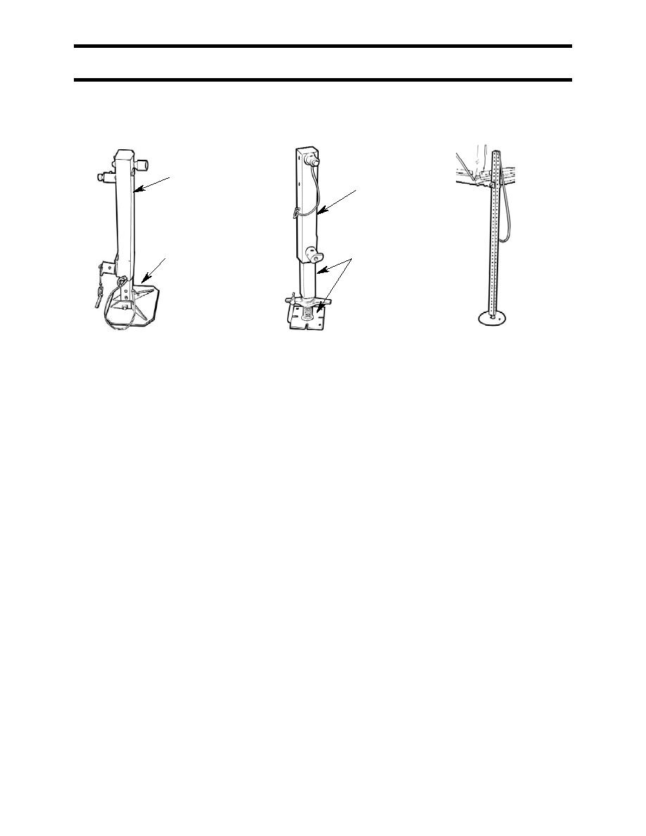
JACK BODY
JACK BODY
EXTENSION/BASE
EXTENSION/BASE
PLATE (2 PIECES)
PLATE (1 PIECE)
WING JACK
CORNER JACK
SCREW JACK
Figure 1. CK Jacks.
5. Referring to Figure 2, insert a corner jack extension/base plate into each corner jack body as
far as it will go. Align the bottom hole in the extension/base plate with the hole in the jack body
and insert the attached locking pin to hold the extension/base plate in place. Using a
jack/winch handle, ensure that the jack mechanisms are rotated fully counter-clockwise
(lowered).
6. In a similar manner, assemble the two screw jacks, ensuring that the adjustment screws are
fully clockwise (lowered).
7. The corner jacks will first be installed at the personnel door end of the container. Referring to
Figure 2, and starting at either corner, attach a corner jack by inserting the studs on the jack
into the end holes in the corner block. Turn the twist lock on the lower stud 90 in either
direction to line up one of the arrows stamped on it with the hole in the stud. Pull the jack back
slightly so the twist lock contacts the inside of the corner block. Insert the attached locking pin
into the twist lock.
8. Repeat step 7 for the other corner jack. Ensure that the twist locks are engaged, all locking
pins are in place, and the jacks are resting parallel to the corner blocks.
9. Locate the bullseye level mounted on the end of the container in a recess in the corner block,
to the left of the personnel access door. Figure 3 shows typical bubble level indications and
what they mean.
0006 00-3
Change 2
