
TM 9-4940-444-14 & P
A10D-1
RENEWAL PARTS AND INSTRUCTION PUBLICATION FOR NEMA SIZE "2"
3 POLE STARTER WITH STANDARD TRIP EUTECTIC OVERLOAD RELAY
NOTE The power unit item 1 consists of a factory
assembly of all the magnetic parts, movable contacts, and
their carrier assembly. This unit usually permits immediate
restoration to service of a device which may have become
inoperative.
Unfasten the two gold colored Hex. Head screws "B", pull
out the power unit, plug-in the new and retighten the screws "B".
A set of stationary contacts is included with the power unit. It is
advisable to install these stationary contacts at the same time,
particularly if visual inspection indicates that both the movable
and stationary contacts need replacement. Specify coil by suffix
letter selected from the coil table on page 65.
Typical Starter Three Pole with Two Circuit Electrical Interlock
RENEWAL OF POWER CONTACTS
INTRODUCTION
The power contacts when used within their rating will
This publication is designed to simplify inspection and
provide long trouble free life. They should not be filed or
maintenance. It features ...
dressed.
1. A publication number keyed to the ordering number of the
1. Remove the power unit assembly by loosening the two gold
device ... to simplify filing and fact finding.
colored slotted hex. head screws "B" and pull the power
2. A nameplate inscription keyed to the specific renewal parts
unit straight out.
publication ... to eliminate cross referencing.
MOVABLE CONTACTS
3. An exploded view for easy, positive identification of parts
2. Remove the contact bar item 30 by removing the two
with illustrated steps on "how to assemble and
screws item 31.
disassemble" ... to conserve time and eliminate guesswork.
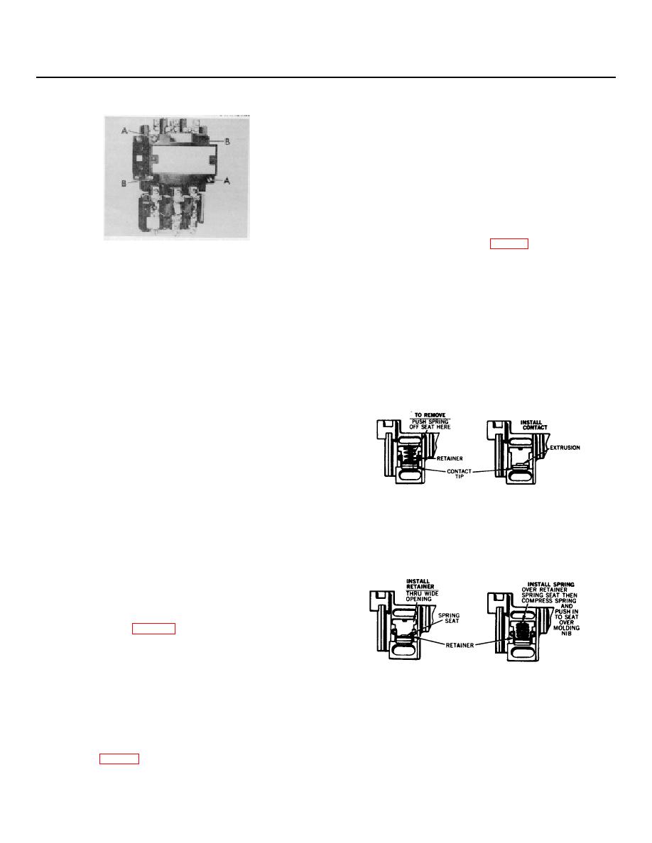
3. Push the springs item 10 off their seat on the retainer item 9
4. Comprehensive maintenance information to provide
and push out. (See sketch "A".)
maximum performance. This information should be read
4. Remove the retainers thru the wide opening in the molding.
carefully.
The contacts item 8 will be free to come out.
DESCRIPTION
These are three pole, three phase, non-reversing A-c
magnetic starters for across the line applications within the
ratings shown on the nameplate of the equipment.
CARE
These starters require no mechanical maintenance. Any
maintenance required can be performed with an electrician's
screwdriver. For continued uninterrupted performance, renew
all of the power contacts and springs at the same time before
SKETCH "A" SKETCH "B"
the contact tip material has worn away.
5. Install the new contacts. (See sketch "B".)
When renewing the contacts check all terminal screws to
6. Install the new retainers, (See sketch "C".) The square
insure they are tight and secure.
openings must be keyed with the extrusions on the
Suggestion - refer to publication 14183 for helpful
contacts.
information on inspecting and determining when to replace
7. Install the springs, insert one end over the seat on the
contacts.
retainer, compress springs and push in to seat over the
RENEWAL OF OPERATING COIL
molding nib. (See sketch "D".)
The operating coil is epoxy encapsulated and so
constructed to provide long service life. Should the coil require
changing, the entire operation can be performed in a few
minutes.
1. Unfasten the two pan head cover screws "A" and remove
the cover item 26 page 63.
2. Unfasten the four pan head screws item 25 securing the
clamp item 24 and the armature item 22. Remove the
clamp and the armature.
SKETCH "C" SKETCH "D"
3. Pull the coil straight out.
8. Install the contact bar to the push bars items 19 and 20 with
4. Install the new coil with the coil terminal blades engaging
screws item 31.
the coil terminal clips.
NOTE: The contact bar is keyed with projections on the
5. Install the armature (narrow end to the right) into its seated
push bars. Match the keys to insure correct fit and
operating position.
6. Install the clamp and secure the screws.
assembly.
7. Install the cover.
RENEWAL OF POWER UNIT
(Continued on Page 65.)
62
