
TM 9-4940-444-14 & P
A50C-1
Continued from page 59.
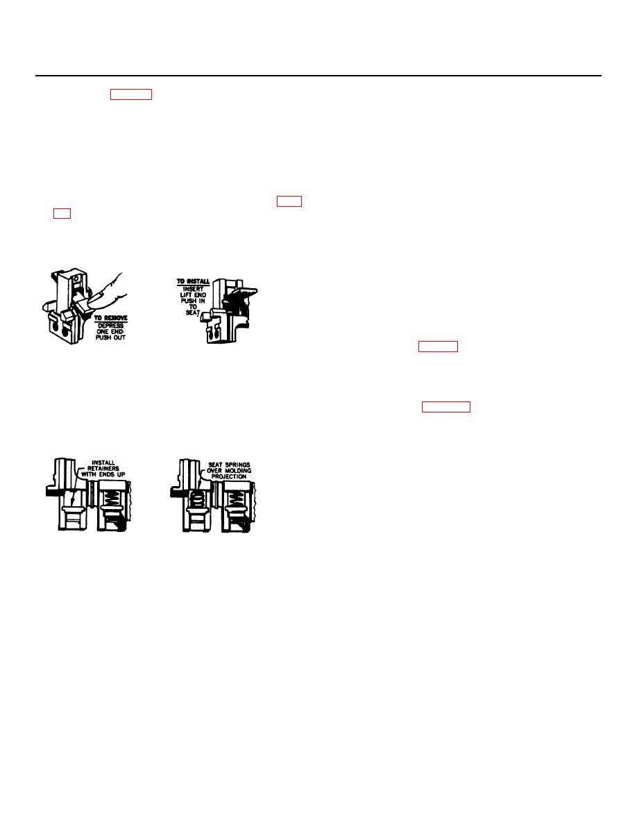
SKETCH "C"
SKETCH "D"
RENEWAL OF POWER CONTACTS
5. Install the new retainers Item 9. (see sketch "C")
The power contacts when used within their rating will
Note-the retainer must be installed so the springs will
provide long trouble free life. They should not be
seat over the extruded hole, with the retainer ends
filed or dressed.
extending away from the contacts.
6. Install the spring Item 10. (see sketch "D").
1. Remove the power unit assembly by loosening the
7. Install the contact (see sketch "B"). Insert contact,
two gold colored slotted hex. head screws "B" and
raise end slightly and push in to seat.
pull the power unit straight out. (See photos on page
STATIONARY CONTACTS
NOTE-It is not necessary to disconnect any wiring.
MOVABLE CONTACTS
8. Remove the screws securing the stationary contacts.
9. Slide the contact out of the groove In the molding. A
hole In the contact plate is provided for convenient
removal with a screwdriver.
10. Install the new contacts.
CAUTION - The stationary contacts must be installed
so they seat on top of the terminal plates. (See
typical assembly page 7.)
SKETCH "A"
SKETCH "B"
ELECTRICAL INTERLOCKS
2. Depress one end of the movable contact and push
The electrical Interlocks are renewable as a complete
the contact out (see sketch "A").
assembly. See page 59 for the various electrical
3. Remove the springs item 10.
interlocks.
4. Remove the retainers item 9.
LUBRICATION
Do not lubricate any part of this equipment.
61
