
01 March 2005
NAVAIR 01-1A-509-3
TM 1-1500-344-23-3
TO 1-1-689-3
Chapter 3), or Sealant Gun (Volume IV or V, Chapter 3)
with nozzle (Volume IV or V, Chapter 3) and retainer
cartridge. Mix sealants in accordance with manufacturer
instructions and form a fillet of sealing compound
around outside edge of antenna base to form a water
tight seal.
j. Check electrical resistance as specified by
applicable aircraft TO/MIM/TM. If no other instructions
apply, use paragraph 6-3.1.12.
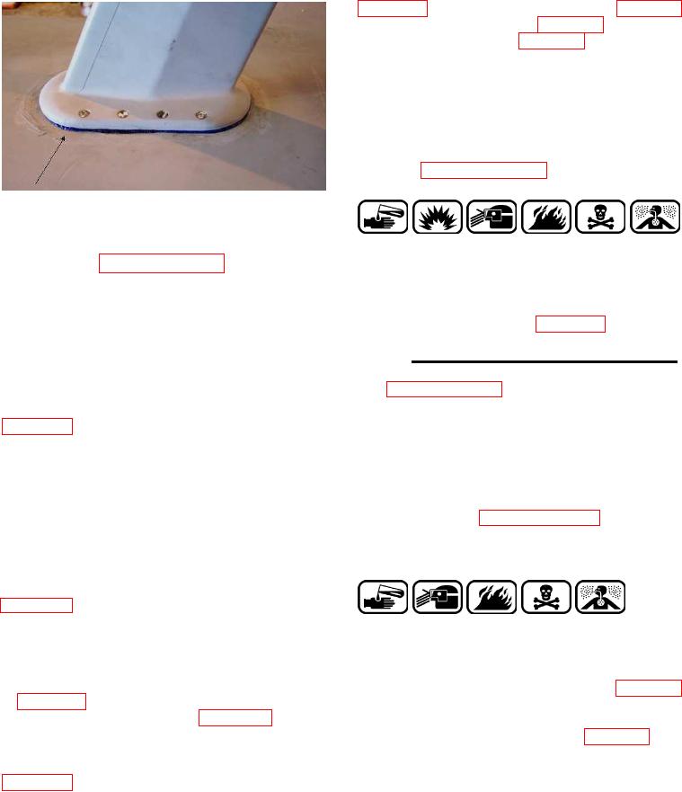
Figure 6-6. Typical Gel Squeeze-Out
Around Perimeter of Antenna
Compound, Corrosion Preventive
8
f. P e r f o r m the electrical resistance test in
MIL-PRF-16173
accordance with paragraph 6-3.1.12. after the antenna
is fully installed or the ground installation is assembled.
k. Cover antenna fastener heads with a thin film of
The test shall take place prior to applying outer edge
MIL-PRF-16173 Grade 4, Corrosion Preventive
sealant, if applicable.
Compound (Volume IV or V, Chapter 2).
g. Inspect antenna mounting fasteners to ensure
6-3.1.4. Alternate Method for Rigid Antenna Mounting.
that the countersink taper area of each fastener head
This method may be used when conductive gaskets
is clean and free of corrosion. If not, use new fasteners.
(see paragraph 6-3.1.3.) are not authorized or available.
Apply thin film of Water Displacing Corrosion Preventive
The following installation procedures, including
Compound, MIL-C-81309 Type III (Volume IV or V,
application of corrosion prevention measures and
Chapter 2), (Air Force can use MIL-L-87177 Grade B
attachment of the antenna to the airframe structure,
as an alternate) to fastener threads prior to installation.
are typical and may be used for mast-type antennas
(blade, spike, whip base, or long wire mast base).
h. Remove release film from the "aircraft side" of
the gasket. Pre-position at least two fasteners through
a. Prepare aircraft skin and antenna mounting area
the antenna base and gasket. Align fasteners at correct
in accordance with paragraph 6-3.1.2.a. through g.
locations on the aircraft surface. Hand tighten each
Remove anodized coating from countersink areas on
fastener one or two turns to hold the antenna in place
new antennas.
on the aircraft. Install remaining fasteners and secure
antenna to aircraft by torquing each fastener in
accordance with specific aircraft TO/MIM/TM.
Figure 6-6 shows an antenna and typical gel
squeeze-out around the perimeter of the antenna
Coating, Chemical Conversion
10
base, after the antenna has been installed.
MIL-DTL-81706
i. For maximum corrosion protection, apply an
b. A p p l y Chemical Conversion Coating,
outer edge seal, Thixoflex Gray Sealant (Volume IV or
MIL-DTL-81706 Class 3 (Volume IV or V, Chapter 2)
V, Chapter 2), with 50 cc Injectable Sealant Application
with Alodine Touch 'n Prep Pen as preferred method,
Dispenser (Volume IV or V, Chapter 3). Or, for
to bare countersink areas in accordance with the
maximum corrosion protection and resistance to aircraft
procedure described in Volume II and Chapter 5. If the
fluid attack on the gasket apply an outer edge seal,
Touch 'n Prep Pen is used, only one coat should be
SAE-AMS-3277 Fast Cure Sealant (Volume IV or V,
applied and the treated surface does not require rinsing
Chapter 2), using Spatula, A-A-277 (Volume IV or V,