TM 55-1945-205-24-4
2-40. WATER HEATER PRESSURE RELIEF VALVE
REMOVAL (Cont)
2.
Ensure water has cooled to a safe temperature.
3.
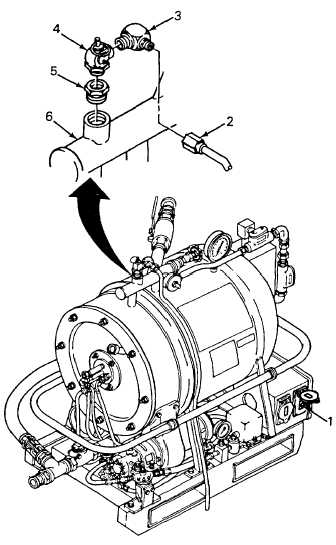
Disconnect overflow tube (2) and elbow (3) from
relief valve (4).
4.
Remove relief valve (4) and bushing (5) from
heater manifold (6).
INSTALLATION
1.
Coat threads of bushing (5) relief valve (4), and
elbow (3) with pipe joint compound (Item 5, App
C).
2.
Install bushing (5) and new relief valve (4) in
heater manifold (6).
3.
Install elbow (3) in relief valve (4) and connect
overflow tube (2) to elbow.
4.
Reconnect power cable. Turn on power switch
(1).
NOTE
FOLLOW-ON MAINTENANCE:
Install tarp assembly (TM 10-2510-209-24).
2-141

