TM 10-3510-220-24
2-23.
WASHER DRIVEBELT (CONT)
INSPECTION (Cont)
6. Install drivebelt cover (1) on mounting brackets using quarter-turn wing head studs (2), turn
studs clockwise until latched.
SERVICE
Lubricate gear reduction unit in accordance with LO 10-3510-220-12.
REPLACE
1. Remove electrical power from the washer.
2. Remove drivebelt cover (1) by disengaging wing head studs (2) from mounting brackets (turn
studs one quarter turn counter-clockwise) and remove studs.
3. Lift upon the drivebelt cover (1), slide cover away from top mounting bracket (2) and remove
cover.
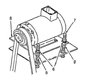
4. Loosen the four locking nuts (6) on motor mounting plate (8).
5. Lower motor and remove old drivebelt. Replace with new drivebelt.
6. Perform ADJUSTMENT procedures as follows.
ADJUSTMENT
WARNING
High voltage is present on this equipment Do not perform maintenance
with power on. Death or serious injury may result.
1. Remove electrical power
from washer.
2. Remove drivebelt cover (1)
by disengaging wing head
studs (2) from mounting
brackets (turn studs one
quarter turn counter-
clockwise) and pulling
studs out.
3. Back-off nuts (6) to finger
tight.
CAUTION
After adjusting belt ten-
sion motor must be level to
prevent excessive belt wear
caused by improper sheave
alignment.
4. Increase belt tension by
evenly turning the four
adjusting nuts (9) under
the motor mounting plate
counter-clockwise.
5. Decrease belt tension by
evenly turning the four
adjusting nuts (9) under
the motor mounting plate
clockwise.
2-75