TM 10-3510-220-24
3-21. WATER HEATER UVSCANNERAND FLAME SAFEGUARD ASSEMBLY
TEST (Cont)
9.
10.
11.
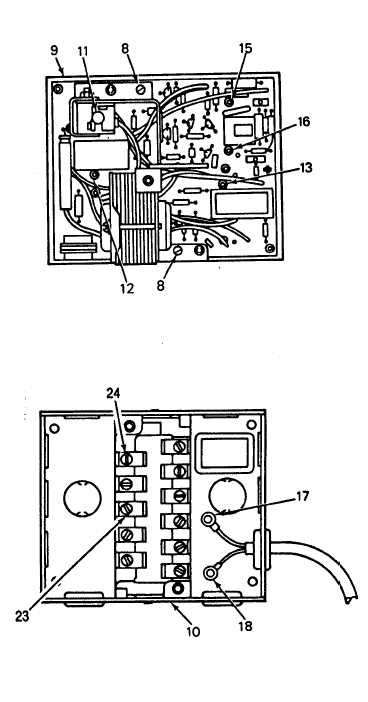
Turn on load limit switch and check
for 120 V ac on terminals (23) and (24)
of base terminal board (10). If
voltage is not normal, disconnect
power source and replace load limit
switch (para 3-20, DISASSEMBLY,
step 2). If voltage at terminals 2 and
7 is normal, install flame safeguard
control circuit card (9) and two screws (8).
NOTE
If the buzzer sounds, an ignition
failure is indicated.
NOTE
Unit maintenance has determined
that ignition takes place momen-
tarily but system shuts down
immediately after ignition.
With multimeter set for dc
operation, set load limit switch to
ON and press reset pushbutton (11)
and check voltage at test points
(15) and (16). If voltage is not 5
to 6 V dc, replace UV scanner.
NOTE
Unit maintenance has determined
that ignition does not occur after
pressing reset pushbutton but
buzzer sounds.
With multimeter set for ac
operation, set load limit switch to
ON and check for 120 V ac at test
points (12) and (13) after pressing
reset pushbutton (11). If voltage
is zero, replace flame safeguard
control circuit card (9).
NOTE
Callouts (23) and (24) are
actually terminals 2 and 7
respectively.
3-102