TM 10--3510--221--24
0251 00--2
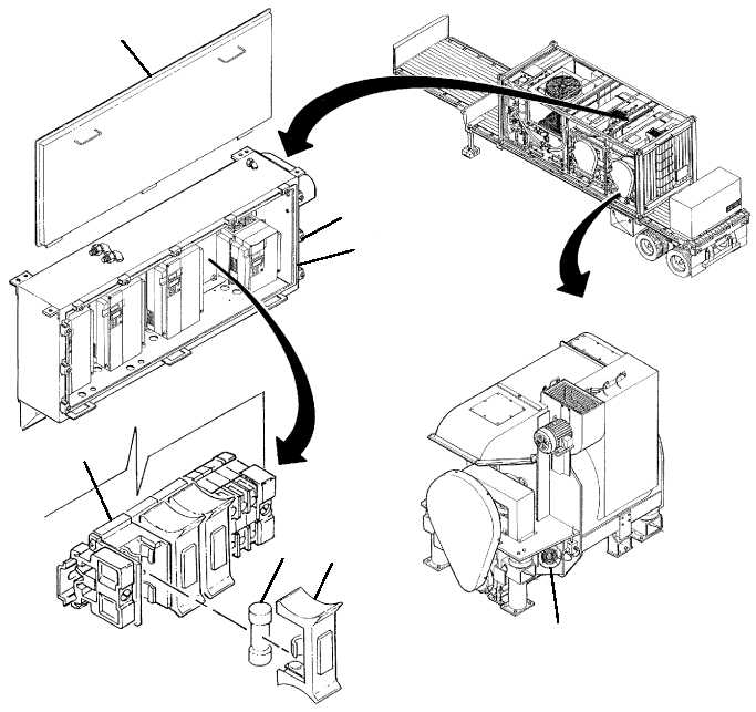
FUSE REPLACEMENT -- Continued
0251 00
3
1
2
5
6
4
7
INSTALLATION
1. Insert new fuse (6) into blown fuse indicator (4).
2. Install blown fuse indicator (4) onto fuse block (5).
3. Place door (2) onto inverter enclosure (3), then secure by tightening eleven latches (1).
4. Position MAIN DISCONNECT switch (WP 0009 00, Figure 1, 1) to ON. Verify cooling fans for inverter
enclosure (3) and drum motors (7) are operating.
END OF WORK PACKAGE