
TM 10-3510-226-23
0024 00
REPLACE
Replace Exhaust Fan
WARNING
This equipment operates at high voltages. Use extreme caution, observe all warnings,
and follow all safety procedures. Failure to observe safety precautions may result in
injury or death to personnel.
1. Switch circuit breaker No. 21 to OFF.
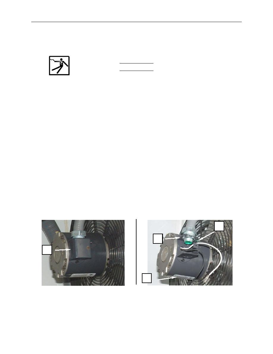
2. Remove screws retaining junction box cover (Figure 3, Item 1) and remove cover.
3. Tag and disconnect wiring from fan (Figure 3, Item 4). The wiring may need to be cut.
4. Remove conduit locknut (Figure 3, Item 7) and remove conduit from junction box (Figure 3, Item 8).
5. Remove screws retaining louver assembly with fan (Figure 4, Item 9) to bulkhead, and remove
louver assembly with fan.
6. Install new louver assembly with fan (Figure 4, Item 9) and secure with screws to bulkhead.
7. Remove screws retaining junction box cover (Figure 3, Item 1) from replacement fan (Figure 3, Item
4) and remove cover. If necessary, punch out the junction box penetration on the replacement fan.
8. Install conduit into junction box (Figure 4, Item 8) and retain with locknut (Figure 4, Item 7).
9. Connect wiring to fan (Figure 4, Item 4) as tagged.
10. Install junction box cover (Figure 4, Item 1) and retain with screws.
11. Switch circuit breaker No. 21 ON and monitor for normal operation.
8
7
1
4
Figure 3. Replace the Exhaust Fan.
0024 00-4
