TM 10-3510-226-23
0029 00
REPLACE-CONTINUED
7. Unscrew the CPVC unions (Figure 2, Item 6) and any attached pipe from the actuator valve (Figure
2, Item 7).
8. Remove the actuator identification tag (Figure 2, Item 8) and place it on the replacement actuator
valve (Figure 2, Item 7).
9. Apply anti-seize tape or pipe sealant to threads of CPVC union halves (Figure 2, Item 6) and screw
union halves into replacement actuator valve (Figure 2, Item 7).
10. Install bracket (Figure 2, Item 5) to replacement actuator (Figure 2, Item 2).
11. Install replacement actuator (Figure 2, Item 2) with bracket (Figure 2, Item 5) as an assembly onto
the wall mount, and retain in place with screws. Do not tighten.
12. Connect CPVC unions (Figure 2, Item 6) ensuring O-rings (Figure 2, Item 9) are in place. Then,
tighten mounting screws.
13. Install the position indicator/handle (Figure 2, Item 3) screw.
14. Connect the electrical quick disconnect (Figure 2, Item 4). Secure the electrical quick disconnect in
place with wire ties.
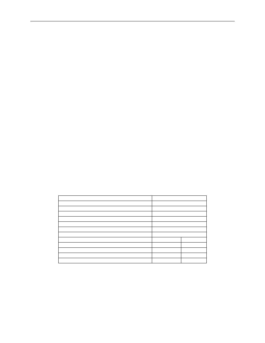
15. Prepare the system for operation by setting valve IAW Table 3.
16. Operate the system IAW procedures given in TM 10-3510-226-10, and monitor for normal operation.
Table 3. Valve Settings to Isolate and Drain Actuator Valve Assemblies.
For Actuator Valve Assembly A-1
Open Valve:
V-41
V-42
Close Valve:
V-28
For Actuator Valve Assembly A-2, A-3, A-4
Open Valve:
V-43
Close Valve:
V-25
V-47
V-30
V-48
V-31
V-50
V-32
V-51
V-46
V-52
0029 00-4


