
TM 10-3510-226-23
0061 00
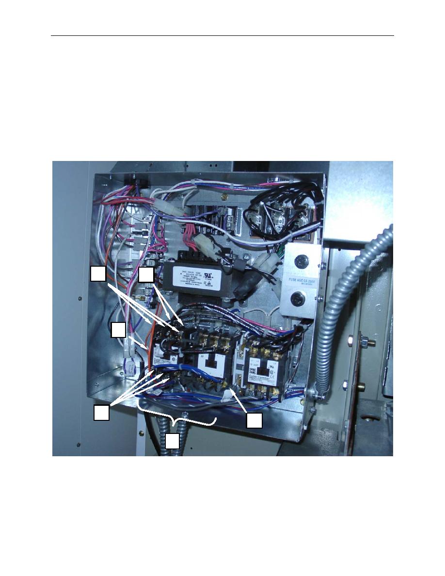
TEST-CONTINUED
9. Disconnect the white and red wires (Figure 2, Item 4) from the contactor control circuit, and use an
ohmmeter to test for 3 to 5 ohms across the two terminals. Replace an open contactor.
10. Reconnect the white and red wires (Figure 2, Item 4) to the contactor control circuit terminals.
11. Perform steps 9 and 10 on the remaining contactor.
12. Install contactor box cover, and retain with screws.
13. Connect power, operate IAW procedures given in TM 10-3510-226-10, and monitor for normal
operation.
3
4
5
2
6
7
Figure 2. Test the Reversing Contactor.
0061 00-4
