TM 5-6350-255-13
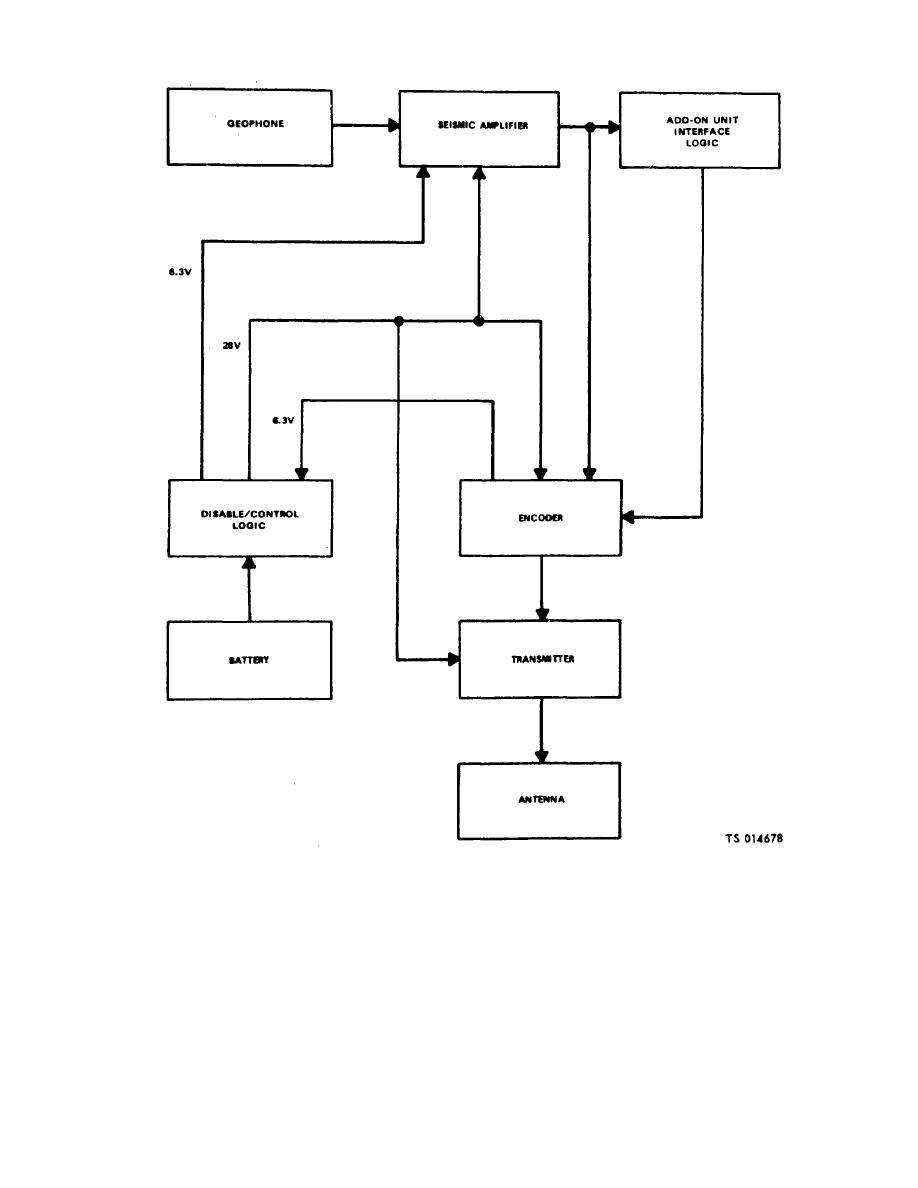
Figure 1-3. Functional block diagram (Models AN/GSQ-154 (V) and AN/GSQ-154A (V).
c. When the unit is implanted the geophone senses
bit code sequence contains 9 bits of synchronizing data,
ground movements and sends the signals to the seismic
2 bits of data to identify the mode (MINISID III or add-
amplifier. The seismic amplifier amplifies and processes
on), 6 bits of address identification for the particular
these signals to characterize them and to determine
MINISID III unit, and a parity bit. The transmitter delivers
when a proper signal is found. The seismic amplifier
a minimum of 2 watts of rf output power to the antenna.
module then sends an alarm signal to the encoder
The total sequence can occur once every 10 seconds
module which controls the application of power from the
with the data message transmitting time being
battery to the transmitter module.
approximately 70 milliseconds long.
d. The code plug provides the inputs to the encoder
The encoder module also generates an 18-bit code
which frequency modulates the transmitter. The 18
1-5


