
TM 9-4940-444-14 & P
A10C-1
Continued from p 52
Reset and tripped indication -
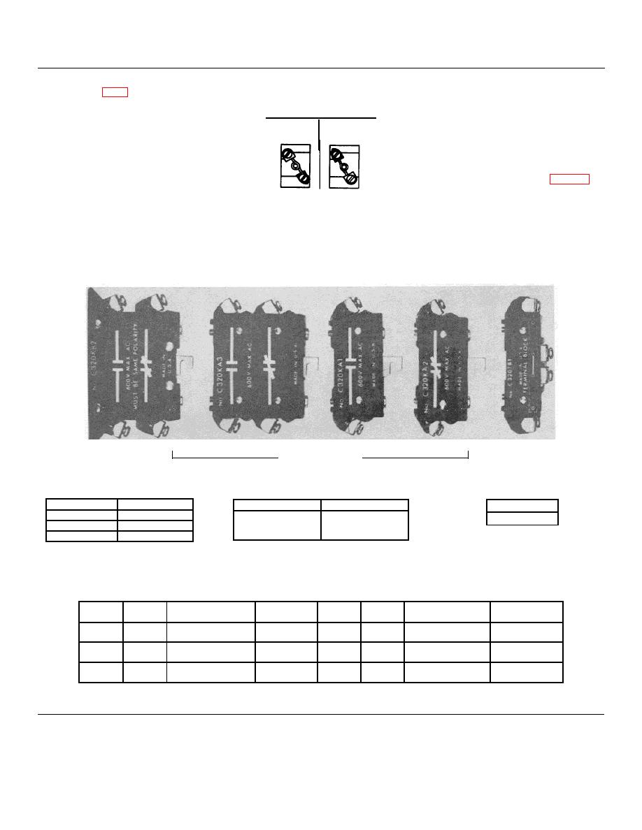
HEATER COIL POSITION
A transparent rectangular window
EUTECTIC OVERLOAD RELAY
above the reset button provides visual
LOW
HIGH
indication.
This overload relay has two steps of
adjustment (low or high) obtained by
POSITIONING THE HEATER COILS as
shown in the adjacent illustrations. Note
Do not disassemble this relay.
the location of the pointed terminal on
The parts called out on page 53 are
the heater coil.
available for repairs.
If parts are
The heater coil selection table
required other than those listed replaced
furnished with the starter illustrates the
the complete relay.
proper mounting position. All coils must
be mounted in the same position for a
given overload relay.
ELECTRICAL INTERLOCKS, TERMINAL BLOCK AND COIL TABLE
ADD ON TYPE
BASE MOUNTED
FOR MOUNTING ABOVE BASE
TERMINAL
MOUNTED INTERLOCK
BLOCK
Circuit
Catalog No.
Circuit
Catalog Number
Cat. No.
None (Dummy)
10-3640-3
1 N.O.
C320KA1
C320TB1
1 N.C.
C320KA2
1 N.O.
C320KB1
1 N.O.-1 N.C.
C320KA3
1 N.O.-1 N.C.
C320KB2
Operating Coils Selection Table
*
*
Volts
Cycles
Part Number
Suffix Letter
Volts
Cycles
Part Number
Suffix Letter
120
60
9-1887-1
A
600
60
9-1887-4
D
110
50
550
50
240
60
9-1887-2
B
208
60
9-1887-5
E
220
50
480
60
9-1887-3
C
380
50
9-1887-8
L
440
50
*Suffix letter required only when power unit is ordered.
Made in U.S.A.
55
