
TM 9-4940-444-14 & P
A50C-1
969
RENEWAL PARTS AND INSTRUCTION PUBLICATION FOR NEMA SIZE "1" 3 POLE THREE PHASE REVERSING
STARTER WITH STANDARD TRIP EUTECTIC OVERLOAD RELAY
INTRODUCTION
This publication Is designed to simplify Inspection and
maintenance. It features...
1. A publication number keyed to the ordering number of the
device...to simplify filing and fact finding.
2. A nameplate inscription keyed to the specific renewal parts
publication...to eliminate cross referencing.
3. An exploded view for easy, positive identification of parts
with illustrated step on "'how to assemble and
disassemble"...to conserve time and eliminate guesswork.
4. Comprehensive maintenance information to provide
maximum performance. This information should be read
carefully.
DESCRIPTION
6. Install the new coil with the coil terminal blades engaging
These are three pole, three phase, reversing A-c magnetic
the coil terminal clips.
starters for across the line applications within the ratings shown
7. Install and seat the spring plate.
on the nameplate of the equipment.
8. Slide the armature (narrow end to the right) into Its seated
CARE
operating position.
These starters require no mechanical maintenance. Any
9. Install the cover.
maintenance required can be performed with an electricians
RENEWAL OF POWER UNIT NOTE
screwdriver. For continued uninterrupted performance, renew
The power unit item 1 consists of a factory assembly of all
all of the power contacts and springs at the same time before
the magnetic parts, movable contacts, and their carrier
the contact tip material has worn away.
assembly. This unit usually permits immediate restoration to
When renewing the contacts check all terminal screws to ensure
service of a device which may have become inoperative.
they are tight and secure.
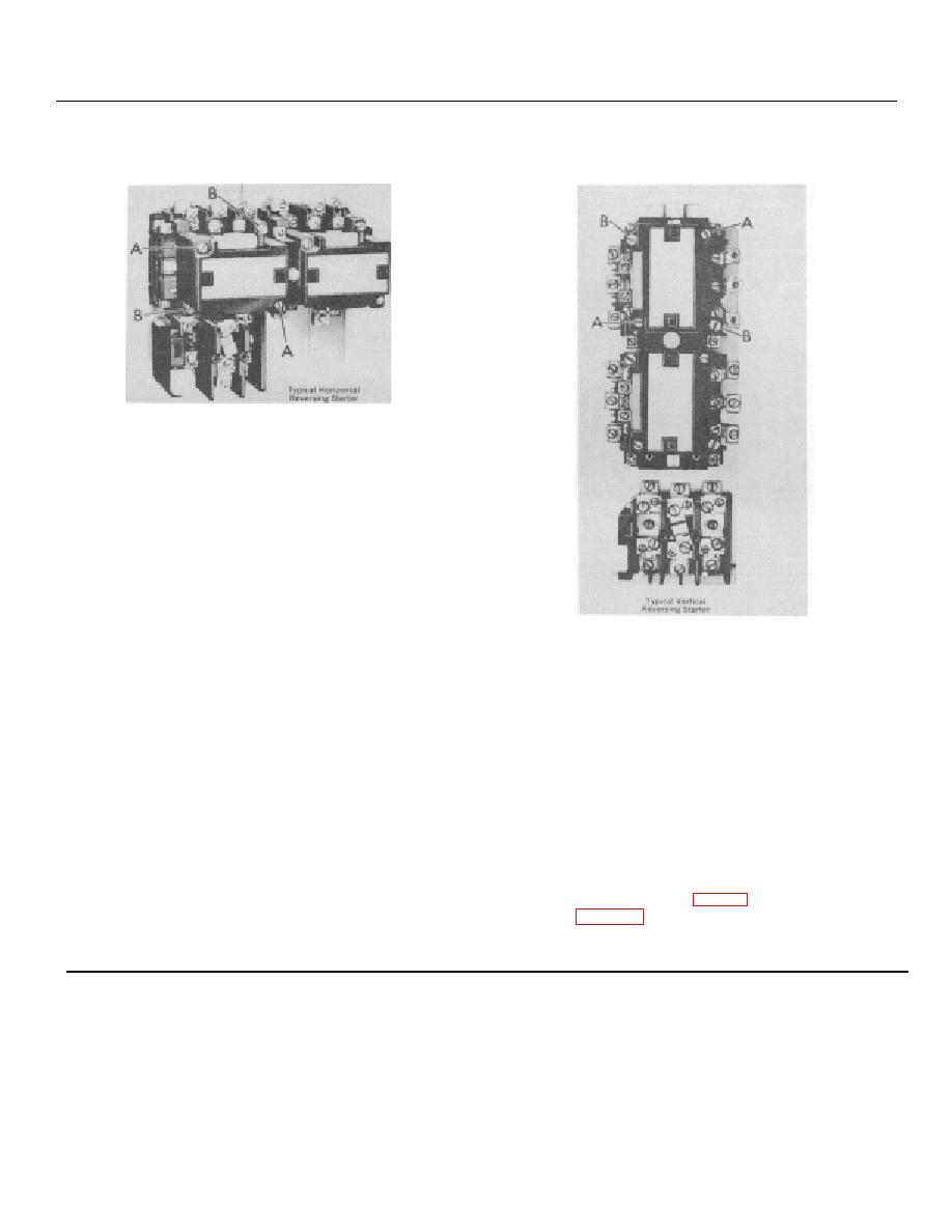
Unfasten the two gold colored Hex. Head screws "B", pull out
RENEWAL OF OPERATING COIL
the power unit, plug-in the new and retighten the screws 'B". A
The operating coil is epoxy encapsulated and so constructed to
set of stationary contacts is included with the power unit. It is
provide long service life. Should the coil require changing, the
advisable to install these stationary contacts at the same time,
entire operation can be performed in a few minutes.
particularly if visual inspection indicates that both the movable
1. Unfasten the two pan head cover screws "A" and remove
and stationary contacts need replacement. Specify coil by suffix
the cover item 16.
letter selected from coil table on page 59.
2. Tilt the top of the armature item 11 away from the coil.
Continued on page 59
3. Slide the armature up and out.
4. Remove the spring plate item 12.
5. Pull the coil straight out.
Made in U.S.A.
56
