
TM 10-3510-208-12
TS 3510-208-12/4-50
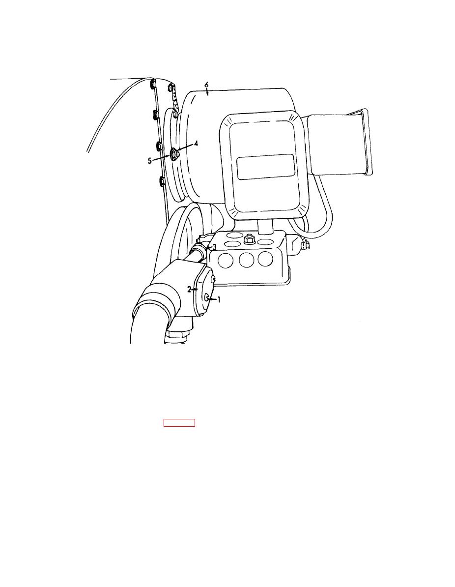
4. Nut
1. Screw
5. Lockwasher
2. Cover
3. Conduit
6. Burner assembly
Figure 4-50. Tumbler burner assembly, removal and installation.
b. Disassembly.
(5) Remove the nuts (19), lockwashers (20)
(1) Remove the tube nut (1, fig. 4-51), drain
and screws (21) securing the valve solenoid (22) to
cock (2) and bushing (3) from the tee.
the solenoid bracket.
(2) Remove the elbow (4), bushing (5) and tee
(6) Remove the screws (23), lockwashers (24)
(6) from the pressure gage.
and peep hole bushing (25) securing the electrode
(3) Remove the screws (7) and lockwashers (8)
cover (26) to the burner base.
securing the pressure gage (9) to the solenoid
(7) Remove the washer (27), peep hole glass
bracket.
(28) and pipe nipple (29) from the burner base.
NOTE
(8) Disconnect the electrode leads from the
When disconnecting elbow (17) with power cable
electrodes.
(18) below, also disconnect from handy box (43).
(9) Remove the bushing (30) from the burner
(4) Remove the hose (10), connector (11),
base.
glove valve (12), elbow (13), nipple (14), bushings
(10) Remove the nuts (31), lockwashers (32)
(15 and 16) and elbow (17) with power cable (18)
and bolts (33) securing the solenoid bracket (34) to
from the valve solenoid.
the plenum chamber.
4-63
