TM 10-3510-208-12
TS 10-3510-208-12/4-68 (Sheet 3 of 3)
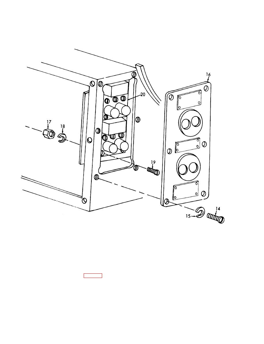
18. Lockwasher
14. Screw
19. Screw
15. Lockwasher
20. Relay switch ays
16. Cover
17. Nut
Figure 4-68. Tumbler controls, removal and installation (sheet 3 of 3).
(5) Remove screws (10) and terminal clamps
b. Disassembly.
(11) securing the contacts (12) to the relay switch
(1) Remove the screws (1, fig. 4-69) securing
boxes.
the the box (2) to the control panel (7).
(6) Remove screws (13) securing the contacts
(2) Remove the screws (3) securing the relay
(14) to the relay switch boxes.
(4) to the control panel.
(7) Remove the contacts (15) by pulling out
(3) Remove the screws (5) securing the ter-
from the retaining clips, then remove the contact
minal block (6) to the control panel (7).
springs (16) which are below the contacts.
(4) Remove the screws (8) and remove the
thermal release heaters (9) from the relay switch
boxes.
4-94


