
TM 10-3510-208-12
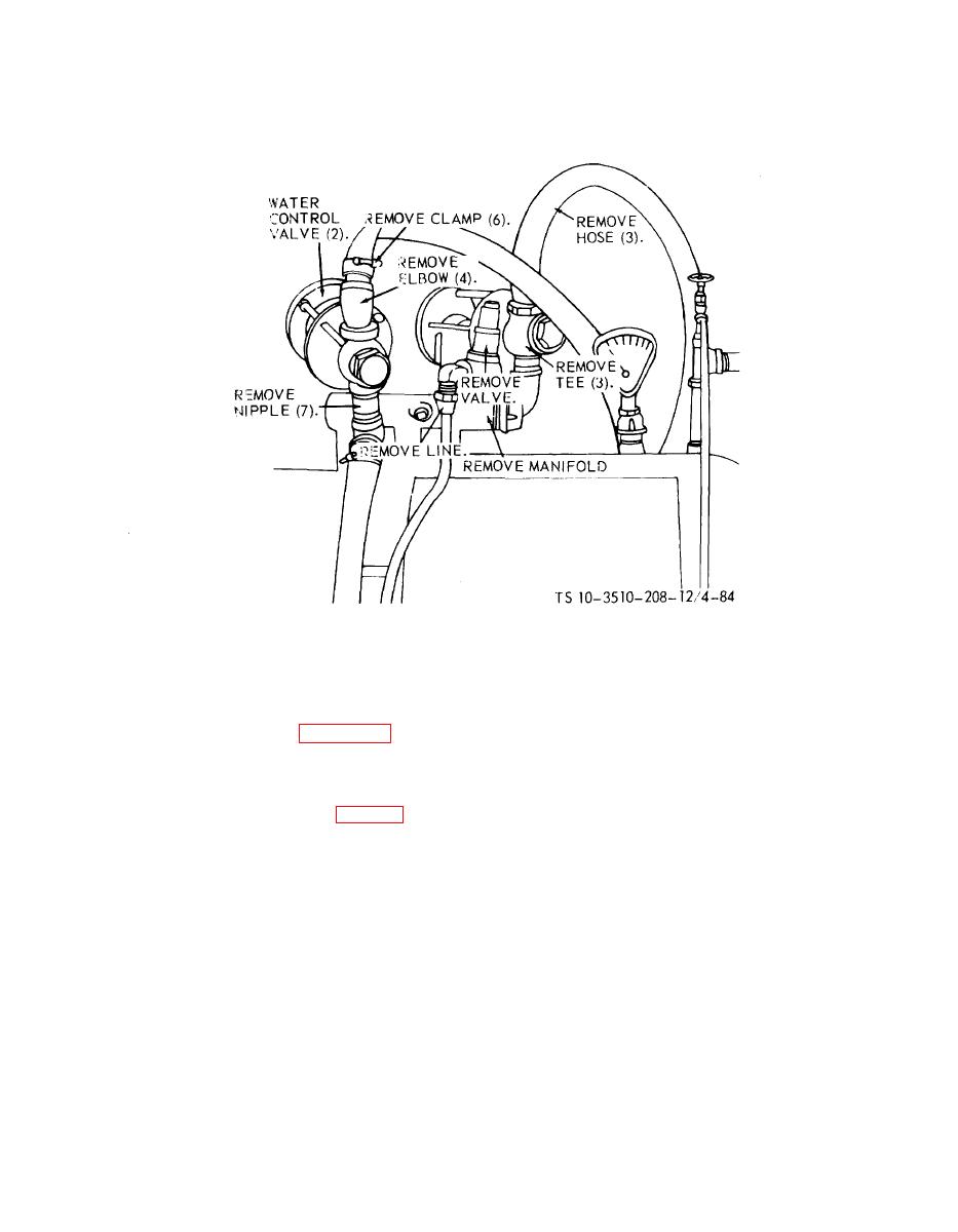
Figure 4-84. Water control valve lines, and fittings, remoual and installation.
b. Cleaning. Clean all lines using a clean cloth.
securing the switch fingers (6) and water level
c. Inspection and Repair.
switches (7) to the switch mounting plate.
(1) Inspect all lines and fittings for damage.
(5) Remove the bolts (8) and lockwashers (9)
(2) Replace all damaged lines and fittings.
securing the switch mounting plate (10) to the
plate separators.
the water control fittings and valve lines.
(6) Remove the screws (11) and lockwashers ,
(12) securing the plate separators (13) to the cover
4-65. Water Level Plates and Tubes
plate.
a. Removal and Disassembly.
(7) Remove the nuts (14) and lockwashers (15)
from the air tubes.
the water level control cover (2) to water level
(8) Remove the screws (16) and lockwashers
control assembly.
(17) securing the cover plate (18) to the water
(2) Tag and disconnect all wiring going to the
container.
water level control assembly.
(9) Remove the lockwashers (19), nuts (20)
(3) Disconnect the two hoses (3) from the
and tube separator (21) from the water level air
water level switches and the water level air tubes.
tubes (22).
(4) Remove the screws (4) and lockwashers (5)
4-119
