TM 10-3510-208-34
parts damaged beyond repair.
(2)
Inspect
all
hardware
for
thread
damage. replace as necessary.
e.
Assembly.
(1)
Insert locking clip (11, fig. 3-8) in hole
provided in flange (12) and install spring (10) and spring
seats (9) on locking clip (11) and secure with cotter pin
(8).
(2) Install flue elbow (7) in flange and secure with
screws (6).
(3) Insert sprout (5) into flow elbow (7) into flue elbow
(7). Position retaining assembly (4) and secure with
screw (3), lockwasher (2) and nut (1).
f. Installation. Position the tumbler exchange
duct assembly (3. Fig 3-7) on the dryer tumbler secure
with lockwashers (2) and bolts (1).
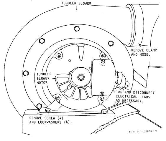
3-6. Tumbler Blower and Motor
a.
Removal. Refer to figure 3-9 tumbler blower
and motor
Figure 3-9. Tumbler blower and motor, removal and installation.
b.
Disassembly.
(1)
Remove the thumbscrew (1, fig. 3-
10) securing the shutter (2) to the air intake housing.
(2)
Remove the bolts (3) and lockwashers
(4) securing the air intake housing (5) and its filter
screen (6) to the blower housing.
(3)
Remove the bolts (7) and lockwashers
(81 securing the blower housing (9) to the flange (17).
(4)
Remove the setscrew (10) securing
the coupling (11) to the motor shaft.
(5)
Remove the setscrews (12) securing
the blower impeller (13) to the motor shaft.
3-13