TM 10-3510-209-24
3-22. WATER HEATER UV SCANNER AND FLAME SAFEGUARD ASSEMBLY (CONT)
SERVICE
1.
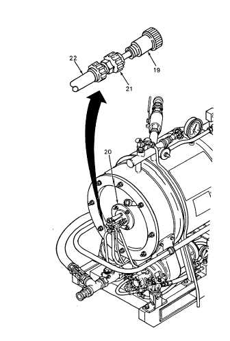
Disconnect UV scanner (19) at burner head
assembly (20) and clean scanner lens with a
clean dry cloth (Item 3, App C).
2.
Connect UV scanner (19) to burner head
assembly.
REPAIR
NOTE
Repair the UV scanner and flame
safeguard assembly by replacing
defective components.
REPLACEMENT
1.
Remove two screws (8) and flame safeguard
control circuit card (9).
2.
Tag and disconnect two wires (17) and (18) from
terminals S1 and S2 on base terminal board
(10).
3.
Disconnect UV scanner (19) at burner head
assembly (20) and remove conduit nut (21). Pull
UV scanner and wires from conduit (22).
4.
Install UV scanner (19) with wires in conduit (22)
and secure with conduit nut (21). Install UV
scanner on burner head assembly (20).
5.
Connect wires (17) and (18) to terminals S1 and
S2 on base terminal board (10). Remove tags.
6.
Install flame safeguard control circuit card (9)
and secure with two screws (8).
NOTE
FOLLOW-ON-MAINTENANCE:
Install
tarp
assembly
(TM 10-3510-209-10.
3-107


