TM 10--3510--221--10
0008 00--4
LAUNDRY ADVANCED SYSTEM DESCRIPTION AND USE OF
OPERATOR CONTROLS AND INDICATORS -- Continued
0008 00
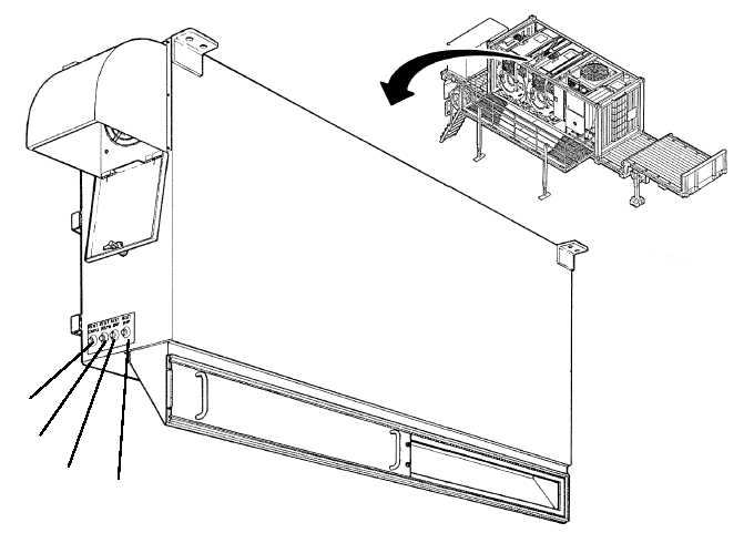
INVERTER ENCLOSURE CONTROLS
Figure 3 shows the location of the controls found on the inverter enclosure. Table 3 describes the use of these
controls.
1
2
3
4
Figure 3. Location of Inverter Enclosure Controls.
Table 3. Inverter Enclosure Controls.
INDEX
DESCRIPTION
TYPE
FUNCTION
1
RESET DRUM A
Pushbutton
Switch
Used to reset drum A inverter when a ”DRUM A
INVERTER FAULT” is displayed.
2
RESET DRUM B
Pushbutton
Switch
Used to reset drum B inverter when a ”DRUM B
INVERTER FAULT” is displayed.
3
RESET 20 HP
Pushbutton
Switch
Used to reset a 20 HP inverter when a ”20 HP
INVERTER FAULT” is displayed.
4
RESET 10 HP
Pushbutton
Switch
Used to reset a 10 HP inverter when a ”10 HP
INVERTER FAULT” is displayed.