TM 10--3510--221--24
0235 00--1
16 CHANNEL SSR PCB REPLACEMENT
0235 00
THIS WORK PACKAGE COVERS:
Removal, Installation
INITIAL SETUP:
Maintenance Level
Materials/Parts
Unit
Washer, Lock (Item 17, WP 0275 00)
Tools and Special Tools
Equipment Conditions
Tool Kit, General Mechanics (Item 1, WP 0272 00)
LADS power must be shut off and door opened at
main control enclosure (WP 0112 00).
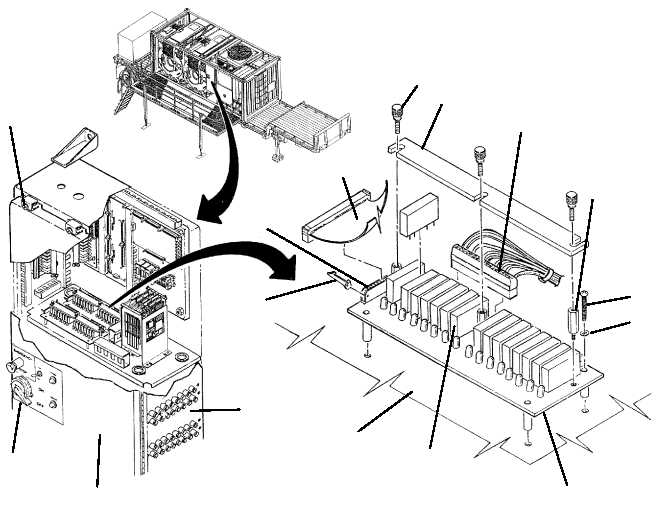
REMOVAL
1. Unplug two wire headers (1) from SSR PCB (2).
2. Disconnect ribbon cable (3) from cable header (4).
3. Remove four screws (5) and lock washers (6), then remove SSR PCB (2) from panel (7).
4. Loosen three thumb screws (8), then remove retaining bar (9).
5. Note position of each SSR (10) then remove SRRs from SSR PCB (2).
16
13
14
15
12
4
3
8
9
1
11
5
6
2
10
7