TM 10-3510-223-13&P
0038 00
0038 00-3/4 Blank
Install
NOTE
Prior to installation of a new float switch, its power cord must be modified
as described in work package 0074, Figure 4.
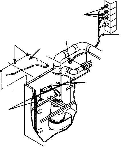
Place new, modified float switch (1) into position onto the interior bracket (2) and install. Float switch
positions are as follows: OFF Switch in 1st position from bottom, ON Switch in 3rd position from bottom,
and ALARM Switch in 7th position from the bottom. Place the power cords into cable clips (3) and install
clips onto tank wall. Feed the appropriate power cord (4) of the new switch through hole in wastewater
tank cover (5). Place wastewater tank lid (6) into position and tighten captive screws (7). Re-connect the
power cables of the three float switches (4) to the appropriately labeled receptacles on the curbside wall
raceway. Secure cords with new cable ties (8). Place circuit breaker #10 in power distribution panel #1 in
the ON position.
END OF WORK PACKAGE
1
2
4
5
6
7
8
3

