
TM 10-7360-226-13&P
0020 00
CONTAINERIZED KITCHEN (WITH TRAILER)
UNIT MAINTENANCE PROCEDURES
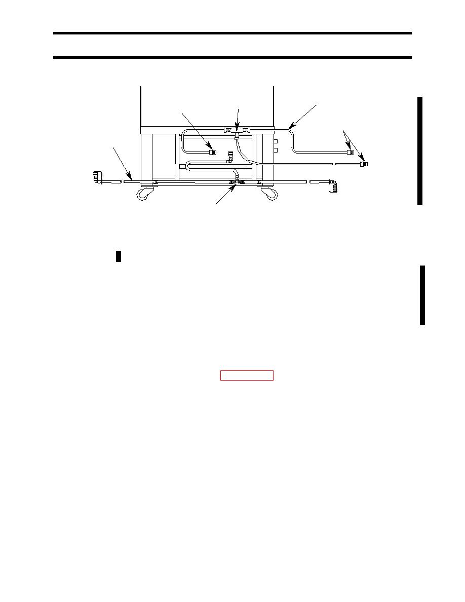
24 VDC
POW ER CABLE
JUNCTION BOX
CONNECTOR
24 VDC
CONNECTORS
FUEL
LINE
TEE CONNECTION
Figure 1. Oven Fuel Line and Power Cable Assemblies.
Fan Switch or Indicator Light: Remove the four attaching screws from the oven control panel
and carefully pull the panel away from the front of the oven. Label and disconnect the wires to
the component (switch or light) being replaced. Note that the indicator light bulb cannot be
separately replaced; the complete light assembly must be replaced. Remove the defective
component and install the new one. Reconnect the wires to the new component and reinstall
the control panel.
REPAIR
MBU Cable Assembly: To replace a section of the 24 VDC cable, remove the junction box
cover (see Figure 1). Label and disconnect the wires and pull the cable through the junction
box. Cut a new cable to the desired length (WP 0045 00 Item 1) and attach a connector to it.
Slip the new cable into the junction box, connect the wires and replace the junction box cover.
24 VDC Connector: To replace a damaged connector, disassemble the connector shell. Label
and disconnect the two wires. Attach the wires to the new connector and assemble it.
MBU: Refer to TM 10-7310-281-13&P for MBU repair procedures.
END OF WORK PACKAGE
Change 1
0020 00-3/4 Blank
