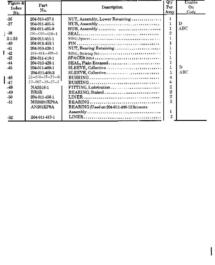
TM 55-1615-226-40
F&iii=E
Index
No.
-36
-37
-38
2-1-39
-40
41
-42
43
-44
45
-46
47
A
49
-50
-51
-52
Part
No.
204-010-437-5
20401140S5
204-011405-9
204-010 -428-1
204-011-411-1
204-011-4531
204-010-420-1
204-011 -409-1
204-011-410-1
204-010428-1
204-011-4081
204-011-408-3
~~_o~()_31_35_4[
~2_O(J7_19_27_1<
NAS5161
13R5R
204-011-456-1
MS20201KP8A
AN201KP8A
204-011-413-1
.— ——
Description
NUT, Assembly, Lower Retaining . . . . . . . . . . . . . .
I-IUB, Assembly . . . . . . . . . . . . . . . . . . . . . . . . . . . . .
HUB, Assembly . . . . . . . . . . . . . . . . . . . . . . . . . . . . . . .
SEAL . . . . . . . . . . . . . . . . . . . . . . . . . . . . . . . . . . . . . . .
RING,Spacer . . . . . . . . . . . . . . . . . . . . . . . . . . . . . . . . . . . . .
PIN . . . . . . . . . . . . . . . . . . . . . . . . . . . . . . . . . . . . . . . . .
NUT, Bearing Retaining . . . . . . . . . . . . . . . . . . . . . .
RING, Bearing Set . . . . . . . . . . . . . . . . . . . . . . . . . . . .
SPACER SM1 . . . . . . . . . . . . . . . . . . . . . . . . . . . . . . . .
SEAL, Plain Encased . . . . . . . . . . . . . . . . . . . . . . . . .
SLEEVE, Collective . . . . . . . . . . . . . . . . . . . . . . . . . .
SLEEVE, Collective . . . . . . . . . . . . . . . . . . . . . . . . . . .
BUSHING . . . . . . . . . . . . . . . . . . . . . . . . . . . . . . . . . . . .
BUSHING . . . . . . . . . . . . . . . . . . . . . . . . . . . . . . . . . .
FITTING, Lubrication . . . .. t... . . . . . . . . . . . . . . .
BEARING, Staked . . . . . . . . . . . . . . . . . . . . . . . . . . .
LINER . . . . . . . . . . . . . . . . . . . . . . . . . . . . . . . . . . . . . .
BEARING . . . . . . . . . . . . . . . . . . . . . . . . . . . . . . . . . . .
BEARING (Used on 204-011-40613 scissors
Assembly . . . . . . . . . . . . . . . . . . . . . . . . . . . . . . . . . . . . . .
LINER . . . . . . . . . . . . . . . . . . . . . . . . . . . . . . . . . . . . . . .
—— —.
‘firm
Per
&
1
1
1
2
1
1
1
1
1
1
1
1
4
4
2
2
2
2
1
2
Usable
on
code
D
ABC
D
ABC
b. Remove the opposite drive link by the same
c. Additional disassembly of scissors is not
procedure.
c. Remove nuts(7), washers (8) and cover plate
(9)from scissors (6).
d. Remove spacer (10)and shim (11). Remove
cotter pin (12) and nut (13) from bolt (14). Remove
bolt, spacers (17 and 18) and washers (15 and 16).
Remove scissors from hub (37).
NOTE
Use wire or tape to secure
bearing (51) in scissors
(6).
e. Remove the opposite scissors by the same
procedure.
2-5. Drive Link
2-6. Disassembly of drive link assembly is not
required except when necessary to replace compo-
nents requiring repair or replacement.
2-7. Scissors.
2-8. Disassemble scissors as follows:
a. Remove liner (19, figure 2-1) from scissors
(6). Use T101424 bar to press out bearing set (20) and
shim (21) from liner (19).
b. Remove shim (22), housing (23) with seal
(71X6223)(24), thrust washer (25) and inner race (26).
required except when necessary to replace compo
nents requiring repair or replacement.
d. When necessary, use T101424 bar to press
out bearings (27 and 29) and spacer (28).
2-9. Hub And Collective Sleeve.
2-10. Disassemble hub and collective sleeve as
follows :
a. Cut and remove lockwire. Remove six bolts
(30, figure 2-1), washers (31), flange (32) and plate set
(33) from top of collective sleeve hub (37). Install
wrench T101392 on hub with two bolts. Invert
assembly and: ecure wrench in a vise.
b. Cut and remove lockwire. Remove two
screws (34) and lock plate (35). Using wrench T101493,
turn lower retaining nut (36) out of hub (37), allowing
nut to remain at lower end of sleeve. Remove
assembly from vise and remove tools.
c. Place assembly upright on a press with
suitable support under hub. Insert smallest end of
ram adapter T101382 in top of sleeve (45) and press
sleeve assembly out of hub (37).
d. Remove seal (38) from hub. Remove spacer
ring (39) from bearing stack.
e. Cut and remove lockwire and remove pin (40,
C h a n g e 22 -3