MODEL 200-A0
CHECKING THE BURNER DRAWER ASSEMBLY
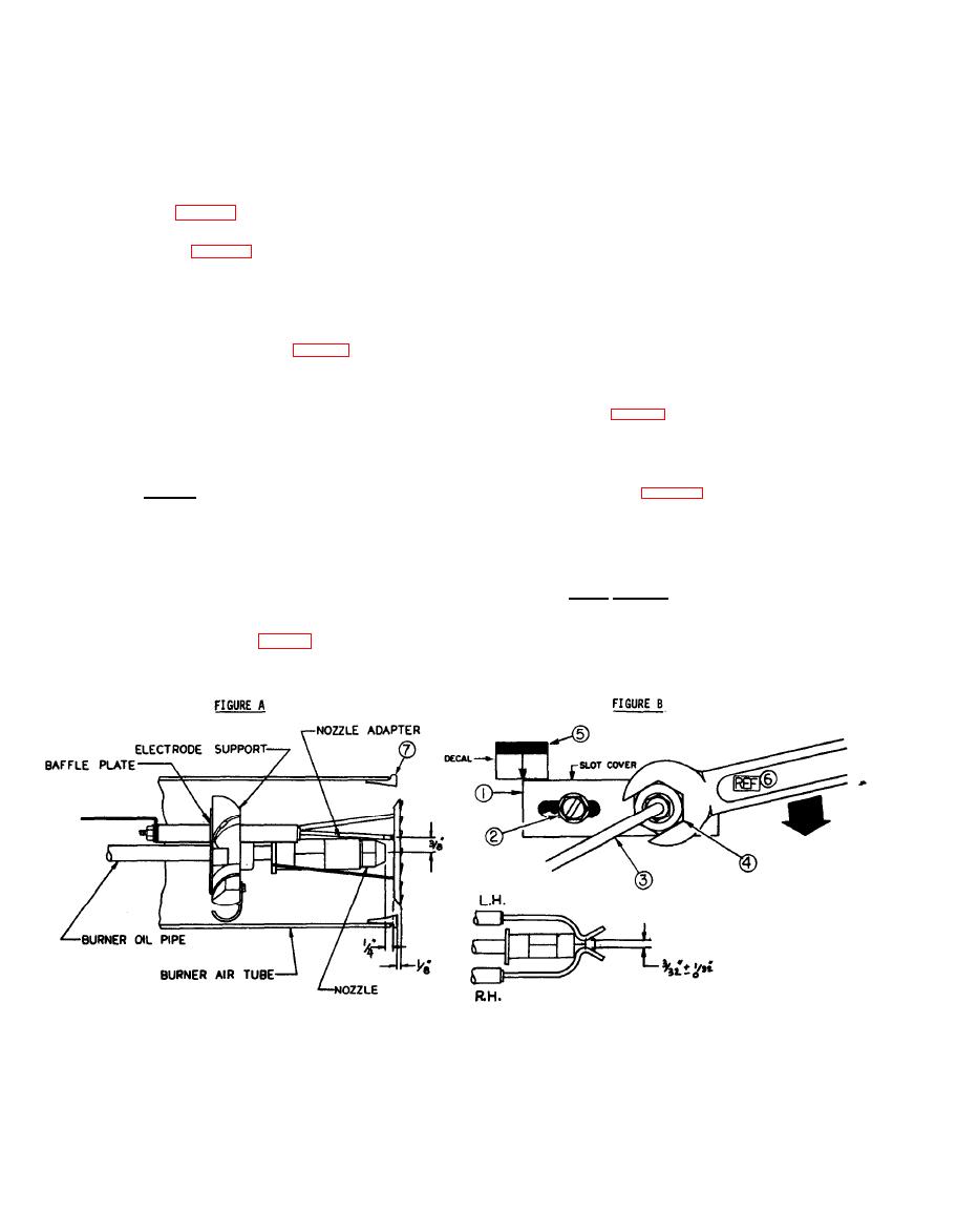
The Burner Drawer Assembly consists of the following items: Fuel Nozzle, Part No. 1175-46-05; Adaptor,
1.
Part No. 1175-33-05; Electrodes, 1175-48-05 & 1175-49-05; Baffle Plate Part No. 1175-31-05; Electrode
Holder, Part No. 1175-29-05; Electrode Leads, Part No. 1175-25-05; Oil Pipe, Part No. 1175-24-05, and
Oil Line Fitting, Part No. 1175-23-05.
2.
Of the above components, only the Fuel Nozzle and Electrodes may require periodic inspection cleaning
and/or replacement. The Drawer Assembly can be readily removed from the Burner Assembly as follows:
(Reference Figures A and B below)
With cleaner secured and disconnected from electrical power source, disconnect 3/16" Copper Tube,
a)
item 3, Figure B, to Burner" at Burner connection, Loosen and remove Pipe Adaptor Locking Nut,
item 4.
b)
Loosen transformer locking clamp enough to permit hinging the transformer on its side and gently
push Drawer Oil Pipe fitting into blower housing. Rotate Drawer Oil Pipe 90 clockwise and "work"
Drawer Assembly Oil Pipe backwards through slot in rear air vane panel until Drawer Assembly can be
removed from Air Tube. Burner Drawer Assembly is now available for "bench" servicing.
c)
The Burner Fuel Nozzle, Figure A, may now be removed for cleanlng or replacement. Never clean
nozzle face with wire brush nor probe orifice with wire or pick, such handling will ruin nozzle.
Clean only with air pressure and/or disassemble and clean in carburetor, small parts cleaner, or
replace with new fuel nozzle.
d)
Check electrode insulators for cracks or shorts, replace as required, see Figure A below for proper
electrode alignment.
e)
Check electrode alignment and position in relation to fuel nozzle tip and centerline. Proper posi-
tion and spacing (gap) is critical to designed burner performance.
CAUTION: During this procedure do not loosen Slot Cover Locking Screw, item 2, Figure B, below, as
the Slot Cover, item 1, positions the Burner Drawer for both Fuel Nozzle and Nozzle Adaptor align-
ment for optimum burner performance. If, for any reason, the Arrow Locator Decal, item 5, is lost
and slot cover is moved, the entire Burner Assembly will have to be removed to properly realign the
Burner Drawer in relation to Air Tube Cone, item 7.
3.
To replace the Burner Drawer Assembly, reverse the procedures as outlined in paragraphs (b) and (a) above.
NOTE : When reattaching Pipe Adaptor Locking Nut, item 4, be sure it is wrench tightened as depicted
below to assure proper centering of the Fuel Nozzle within the Air Tube. Improper fuel nozzle centering
in relation to the Air Tube can result in poor combustion due to flame impingement.
4.
If Nozzle Adaptor (see Figure A below) is removed or replaced. make certain when reinstalling; that the
flat surface stamped "TOP" is in the correct "installed" position. This is a "dribble-proof nozzle
adaptor and will only function as intended when installed properly.


