TM 10-3510-208-12
TS 3510-208-12/4-88
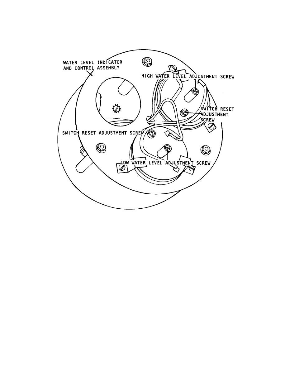
Figure 4-88 Water level indicator and control assembly adjustment.
(2) Adjust switch reset adjustment screw
NOTE
For all adjustments completely drain the washer
(similar step) same as the high level adjust screw
then refill for water level check. The unit water level
above. This adjustment is necessary to assure that
at high setting should be 11 in. (27.94 cm) from in-
pressure switch will reset or close its contacts
side tub surface. The lower end of measuring
during unit draining or water level change,
device is on the tub surface and not housing stud
(3) Adjust (lower) low level adjustments screw
plate. The low level should be 7 in. (17.78cm).
to obtain 7 inch (17.78 cm) water level. Repeat
Tolerances are 1/4 in. (0.64cm).
adjustments until 7 inch level 1/4 inch (17.78
(1) Adjust (upper) high level adjustment
0.64 cm) is obtained.
screw to obtain 11 inch (27.94 cm) water level.
(4) Make similar adjustments in same
Rotation of screw clockwise will increase water
directions on switch reset screw. Adjust until
level, while counterclockwise will decrease water
opening and closing of reset switch insured.
level. One eight (1/8) turn will vary water level
approximately one-fourth (1/4) inch (0.64 cm).
Repeat adjustment until desired level is obtained.
4-125


