TM 10-3510-209-24
2-35. WATER HEATER ELECTRIC CONTROL ASSEMBLY (CONT)
REPAIR (Cont)
(5)
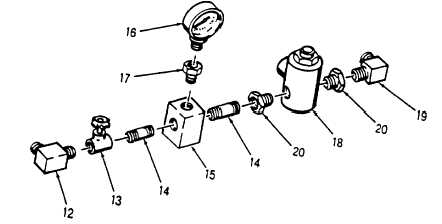
To remove control valve (13), unscrew elbow (12) and unscrew valve from nipple (14).
(6)
To remove fuel line tee (15), repeat steps 5, 6, and 7 if necessary, unscrew two nipples (14).
(7)
To remove gage (16), unscrew gage from snubber (17).
(8)
To remove solenoid valve (18) unscrew elbow (19), two reducers (20), and unscrew solenoid valve.
b.
Assemble fuel supply control assembly as follows:
(1)
Inspect components for damaged threads and broken gage. Replace defective components.
WARNING
Drycleaning solvent, (Item 10, App C) is potentially dangerous. Avoid repeated or
prolonged breathing of vapors and skin contact with liquid. Do not use near open
flame, arcing equipment, or other ignition sources. Use in well ventilated places.
(2)
Clean all used components and fittings with solvent (Item 10, App C).
NOTE
Use thread sealing compound (Item 5, App C) when joining pipes and fittings.
(3)
Install two nipples (14) and snubber (17) in fuel line tee (15) by turning clockwise.
(4)
Install gage (16) in snubber (17) by turning clockwise.
(5)
Attach control valve (13) to nipple (14) by turning clockwise.
(6)
Install elbow (12) to control valve (13) by turning clockwise.
(7)
Install two reducers (20) in solenoid valve (18) and install assembled components to nipple (14).
Install elbow (19) to reducer (20).
2-124.6 Change 1