TM 10-3510-209-24
2-42. DRYER BURNER ASSEMBLY (CONT)
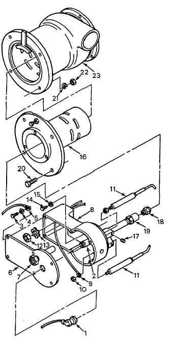
6.
Adjust the burner electrode and fuel nozzle
setting. Refer to ADJUSTMENT, paragraph
2-41.
7.
Install burner base (8) in plenum (16) and
secure with three screws (14) and washers (15).
8.
Install two conduit nuts (13) and two wire
protectors (12).
9.
Connect electrical wires (9) to base of electrode
(11) and secure with two nuts (10).
10.
Install burner cover (6), with sight glass (7)
attached, on burner base (8) and secure with
five screws (3) and washers (4).
11.
Position grounding strap (5) to burner cover (6)
and secure with screw (3) and washer (4).
12.
Install UV scanner cable (1) on UV scanner (2).
Open the fuel shutoff valve.
NOTE
FOLLOW-ON MAINTENANCE:
Install tarp assembly (TM 10-3510209-10).
2-155