TM 10-3510-220-24
2-51.
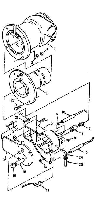
DRYER BURNER ASSEMBLY (CONT)
INSTALLATION (Cont)
6.
7.
8.
9.
Adjust the burner electrode and fuel nozzle
setting. Refer to ADJUSTMENT.
Install burner base (5) in plenum (4) and
secure with three screws (21) and washers
(22).
Install two conduit nuts (17) and sightglass
tube (18).
Connect electrical wires (12) to base of
electrode (10) and secure with two nuts (13).
10. Install sightglass (15) on burner cover (16)
and install burner cover (16), burner base (5)
and secure with six screws (19) and washers
(20).
11. Install UV scanner cable (14) on UV scanner
tube (11). Open the fuel shutoff valve.
12. Install fuel line (25) on elbow (24).
ADJUSTMENT
Refer to ADJUSTMENT, para 2-44.
Perform follow-on installation.
Install tarp assembly (TM 10-3510-220-10).
2-184