TM 10-3510-220-24
3-15. EXTRACTOR ASSEMBLY (CONT)
REPAIR (Cont)
f.
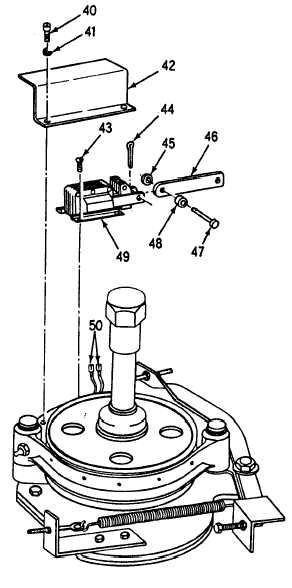
Remove two hex head screws (40),
washers (41), and solenoid shield
(42).
g.
h.
i.
j.
k.
l.
m.
n.
o.
p.
Tag and disconnect wires (50) on
brake solenoid (49).
Straighten and remove cotter pin
(44), three spacers (45), pin (47) and
connector link (46) from brake
solenoid (49).
With a multimeter on the low ohms
scale, measure across the brake
solenoid (49). Multimeter should
indicate approximately 12.5 ohms.
Remove four screws (43) and brake
solenoid (49).
Install new brake solenoid (49) and
secure with four screws (43).
Install connector link (46) on new
brake solenoid (49), and secure with
three spacers (45), pin (47) and
cotter pin (44). Bend end of cotter
pin.
Connect wires (50) to brake solenoid
(49). Remove tags.
Install solenoid shield (42) and
secure with two allen-head screws
(40) and washers (41).
Refer to paragraph 2-29 and adjust
the brake.
Refer to REPAIR, step 1,1 and
install curb on base.
3-60