TM 10-3510-222-24
3-58. DRYER - continued.
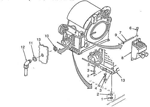
NOTE
Wire numbers are stamped on each electrical wire. This information, in conjunction with data on
FO-4 Dryer A zing Diagram, may be used to connect wires if tags are lost or illegible.
(6)
Route wires to start switch, connect to starter switch (8) as follows and tighten screws (6):
Wire 31
-
L1
Wire 30
-
L2
Wire 29
-
L3
(7)
Connect ground wires to terminal board as follows:
Wire 33
to
TB-8
Wire 32
to
Grounding Lug
(8)
As required, install tiedown straps (9).
(9)
Close cover (Para 3-63).
(10) Install rear frame (Para 2-19).
(11)
Connect fuel input hoses (TM 10-3510-222-10).
Figure 3-54. Dryer
3-137