
TM 10-3510-226-23
0022 00
REPLACE-CONTINUED
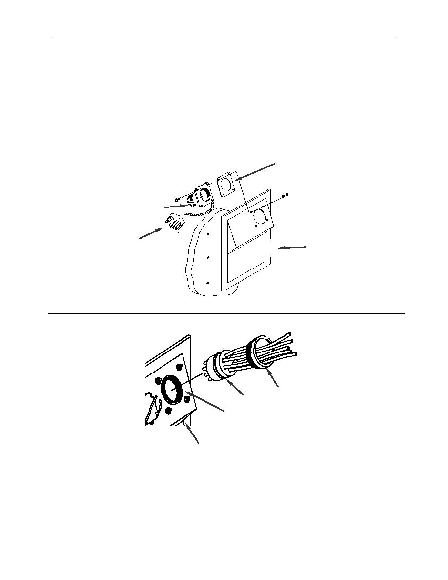
6. Remove screws, washers and nuts securing the connector sleeve (Figure 4, Item 7), gasket (Figure
4, Item 11) and dust cover (Figure 4, Item 12) to the power panel (Figure 4, Item 3). Retain the
hardware.
7. Obtain new power input receptacle (Figure 4, Item 2) and install connector sleeve (Figure 4, Item 7),
gasket (Figure 4, Item 11) and dust cover (Figure 4, Item 12) with retained hardware.
8. From the rear of the power panel (Figure 4, Item 3), push the receptacle (Figure 4, Item 2) into the
sleeve (Figure 4, Item 7) and secure with the retainer (Figure 4, Item 6).
11
7
12
3
6
2
7
3
Figure 4. Replace the Power Output Receptacle.
0022 00-5
