
TM 10-3510-226-23
0022 00
REPLACE-CONTINUED
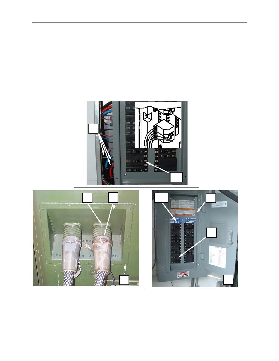
9. Connect the wiring (Figure 5, Item 9) to the circuit breaker (Figure 5, Item 10) as tagged.
10. Reinstall circuit breaker panel cover (Figure 5, Item 5) and circuit breaker box cover (Figure 5, Item
4).
11. Reconnect the power output cable (Figure 5, Item 1) to the receptacle (Figure 5, Item 2) on the CBL
power panel (Figure 5, Item 3).
12. Place main circuit breaker (Figure 5, Item 13) and output circuit breaker (#23, 25, 27) (Figure 5, Item
10) to ON and monitor for normal operation.
9
9
10
1
13
2
5
9
4
3
Figure 5. Replace the Power Output Receptacle.
END OF WORK PACKAGE
0022 00-6
