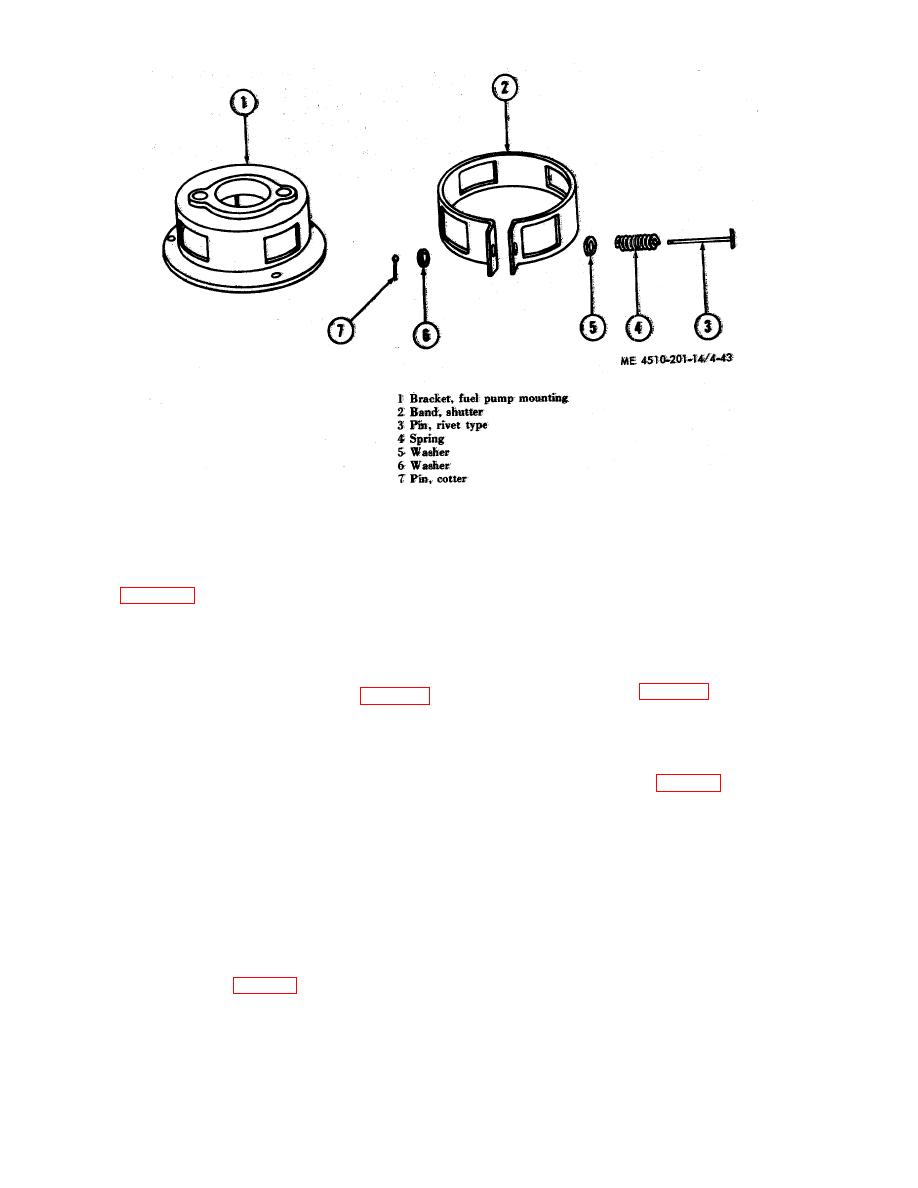
disassembled.
of the fuel pump. Then loosen the strap holding the line
f. Fuel Pump Coupling.
to the bracket, and disconnect the fitting from the control
(1) Removal
valve tee.
(a) Remove
the
blower
shutter
(2) Remove the fuel control valve bypass
assembly (para 4-44b (3) (a)'thru (c)) on Army models
elbow-to-fuel pump return line assembly (4) from the
SPE 35, SPE 35A, and SPE 41.
heater. Disconnect the flared fitting from the tee at the
bottom of the fuel pump, loosen the retaining strap that
(b) Remove. the fuel pump mounting
holds the line to the bracket, and disconnect the fittings
bracket with the shutter (para e (1) (a) thru (c) above)
from the control valve bypass elbow.
on Army Models SPE 44, SPE 45 and York-Shipley
Model YS49279.
(3) Remove the fuel shutoff valve-to-burner
nozzle line assembly (fig. 4-19) by disconnecting the
flared fitting from the fuel shutoff valve and from the
in coupling (19), and slip the coupling from the motor
burner nozzle ,elbow.
shaft.
(4) Remove the manifold-to-pressure control
(2) Inspection. Inspect for broken coupling,
line assembly by unscrewing the fitting on the upper
damaged threads and excessively worn shaft holes.
manifold and unscrewing the fitting: at the temperature
and pressure control (12, fig. 4-22), and sliding the line
(3) Installation. Replace defective coupling
assembly from the clips on the water heater.
with a serviceable one and install it by reversing the
procedure in f (1) above.
d. Installation.
Replace defective fuel line
4-42. Fuel Fittings and Lines
assemblies and fittings with serviceable ones, and install
them by reversing the procedures in c above as
a. Servicing.
Clean
fuel fittings and line
applicable.
assemblies in SD (solvent, dry-cleaning) and dry them
thoroughly.
a. Description. The electric motor is mounted on a
b. Inspection. Inspect for broken, cracked, and
plate in the lower left front of the water heater.
leaking line assemblies, and inspect for stripped or
damaged threads on the fittings.
c. Removal.
(1) Remove the fuel pump-to-fuel control
valve tee line assembly (5, fig. 4-21) from the heater by
disconnecting the flared fitting at the side


