TM 10-3510-220-24
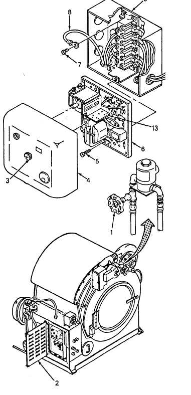
2-48. DRYER UV SCANNER AND FLAME SAFEGUARD ASSEMBLY (CONT)
INSTALLATION (Cont)
2.
3.
4.
5.
6.
7.
8.
9.
10.
Route the wires of UV scanner (10) through
the electrical panel.
Install UV scanner (10) on burner cover (11).
Connect electrical wires (8) to the
terminals on the electrical panel and
install screws (7). Remove tags.
Install purge timing card (13)
on flame safeguard control
chassis (6) if the card is
packed separately.
Install flame safeguarding control
chassis (6) in base (9) and
tighten two screws (5).
Install cover (4) on flame
safeguarding control chassis (6)
and secure with screw (3) in
center of cover (4).
Close door (2) on the dryer electrical
panel and secure with thumbscrews.
Open fuel shutoff valve (1).
Perform follow-on installation.
Install dryer bin (TM 10-3510-220-10).
Install tarp assembly (TM 10-3510-220-10).
2-174

