TM 10-3510-220-24
3-25. DRYER UVSCANNERAND FLAME SAFEGUARD ASSEMBLY (CONT)
SERVICE
1.
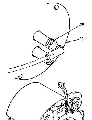
Disconnect UV scanner (25) at burner
head assembly (26) and clean scanner
lens with a clean dry cloth (Item 3, App C).
2.
Connect UV scanner (25) to burner head
assembly (26).
REPAIR
Repair the UV scanner and flame safeguard
assembly by replacing defective components.
REPLACE
1.
2.
3.
4.
5.
6.
WARNING
High voltage is present on this equipment.
Do not perform maintenance with power on.
Death or serious injury may result.
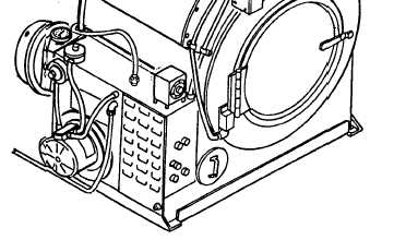
Loosen two screws (10) and flame safeguard
control circuit card (13).
Tag and disconnect two wires (20) and (21) from
terminals S1 and S2 on base terminal board (24).
Disconnect UV scanner (25) at burner head assembly
(26). Pull UV scanner and wires from conduit.
Install UV scanner with wires in conduit.
Install UV scanner on burner head assembly
(26).
Connect wires (20) and (21) to terminals S1 and S2
on base terminal board (24).
Install flame safeguard control circuit card (13) and
secure with two screws (10).
3-117