TM 10--3510--221--24
0141 00--2
FRONT SIDE--TO--SIDE VIBRATION ELIMINATOR
REPLACEMENT -- Continued
0141 00
9
8
10
8
7
2
3
4
5
13
15
14
18
12
17
16
1
6
INSTALLATION
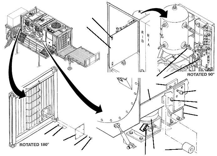
1. Insert vibration eliminator (16) between pre--load plate (14) and bumper support (17). Ensure inner hole on
vibration eliminator is centered over pin (16).
NOTE
When compressing vibration eliminator ensure ends remain square against pre--load plate and bumper
support.
2. Tighten four screws (12) to secure nut plate (13) and pre--load plate (14) to drum frame (15). Tighten screws in
a criss--cross manner.
NOTE
Step 3 applies to right front vibration eliminator on drum B only.
3. Install access panel (10) onto flat rack (11), then secure with eight screws (7), flat washers (8), and nuts (9).
4. Open manual valve (4).
5. Close access door (3) and secure by engaging two latches (2).
6. Perform a test laundry cycle (TM 10--3510--221--10). Verify smooth operation of drum.
END OF WORK PACKAGE

